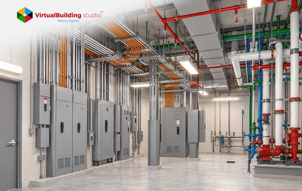
Electrical rooms pack transformers, switchgear, panelboards, and UPS systems into a floor area that keeps shrinking on every project. That equipment cannot be pushed together to save space, because code-mandated working space must stay clear around every panel. Electrical rooms in BIM exist precisely because this clearance is not negotiable, and violating it creates a safety hazard, not just a coordination issue.
Cable trays and conduits compete with ductwork and sprinkler mains for the same overhead space, and beams, columns, and slab depths tighten the room further. When these elements shift late, the effect is significant: a transformer moved to clear a beam can invalidate the clearance in front of an adjacent switchboard, forcing walls and access paths to be redesigned.
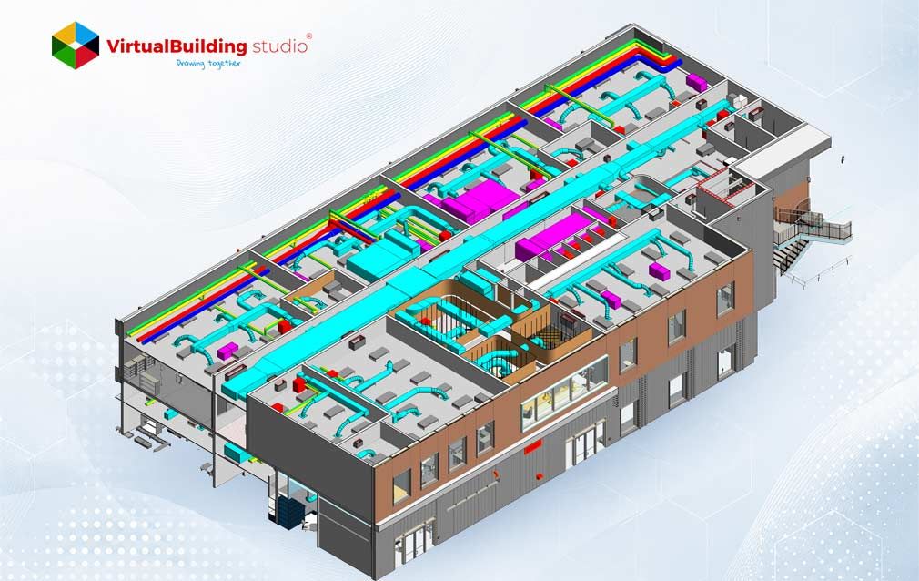
Coordination teams now build this planning into a federated model, where equipment, clearances, structure, and MEP routes get tested against each other before construction begins.
Best Practices for Planning Electrical Rooms Using BIM
Nine practices define electrical room design in BIM, turning that federated model into a working process that starts with the equipment everything else has to fit around.
Start With the Electrical Equipment Layout
Modelers should begin with the equipment, not the containment that connects it. The room's core inventory includes switchgear, transformers, panels, UPS systems, and distribution equipment, and each item carries its own footprint and access needs. Modelers need to capture:
- Equipment dimensions matched to the specified manufacturer, since wrong families distort space requirements across the model
- Equipment orientation, because switchboards frequently need front and rear access
- Required operating space, which manufacturers sometimes set higher than code minimums to allow for future service
Medium-voltage switchgear manufacturers publish minimum aisle widths of 800 mm for standard panels, rising to 1600 mm where a future panel swap is anticipated. Engineers should route containment to follow the equipment layout, not the other way around, since the layout defines every no-go volume raceway design has to respect. Accurate families are the foundation of electrical BIM modeling, and this is the same equipment-first sequence teams follow for Revit electrical modeling on any complex room.
Define Working and Maintenance Clearances
Working space is the next layer, and teams should model it as geometry, not a drawing note. NEC 110.26 sets depth by condition, from 3 to 4 feet for 151 to 600 volt equipment, width equal to the equipment width or 30 inches, whichever is greater, and headroom of 6 feet 6 inches. Dedicated equipment space is a separate zone, floor to 6 feet above the equipment, excluding piping, ductwork, or foreign equipment.
Access extends beyond that envelope, and teams need to account for several additional zones:
- Maintenance zones adding 300 to 600 mm of service-specific buffer beyond code minimums
- Door swing, modeled as a swept volume so open doors don't cut access below 24 inches
- Approach areas, including entrance and egress paths for equipment rated 1,200 amps or more
- Clearance around heat-producing equipment, since transformers and batteries need separation and ventilation
Engineers should run clearance checks inside the model, because a duct that satisfies mechanical requirements can still violate required headroom over a switchboard aisle, and that conflict only becomes visible in three dimensions. This is why electrical equipment coordination depends on clearance geometry being modeled, not just annotated.
Coordinate the Room With the Structural Design
Structural elements define working space conditions directly, and that link is central to electrical room coordination, which is why structure and electrical layout cannot be designed apart. A concrete or brick wall opposite live parts is treated as grounded under NEC 110.26, which pushes a space into a stricter, deeper condition than an open aisle would require.
Beams, columns, and slabs govern the room's vertical budget just as tightly, and headroom minimums, dedicated equipment space, and tray access allowances together consume a typical structural zone fast. Structural teams and BIM coordinators should resolve these interfaces at LOD 350, since that level adds the supports and sleeves earlier design stages leave out. Several items function as coordination deliverables on their own:
- Equipment pads, typically 4 inches high and oversized 4 inches beyond the equipment base on each side
- Sleeves and openings, which crews must locate before slab pours occur
- Equipment anchoring, governed by ASCE 7 seismic design criteria
- Floor loading requirements, commonly specified at a minimum of 150 psf for switchgear areas
With equipment, clearances, and structure aligned, cable tray and conduit routing becomes a solvable geometry problem instead of an ongoing negotiation between trades.
Plan Cable Tray and Conduit Routes Early
Routing engineers should follow the equipment layout established above, never the reverse. Main tray routes come first, following the equipment lineup and entering at designated cable-entry points, with branch routes dropping off those mains. Vertical transitions and riser positions need agreement across floors early, since a riser that moves later drags every horizontal main it feeds.
Conduit banks add geometric constraints that flat drawings tend to hide:
- Bend limits capping total bends at 360 degrees between pull points, counting every offset and saddle
- Penetrations through rated assemblies, each requiring a tested firestop system
- Installation access, with the 2026 NEC requiring 12 inches of clear space above cable trays
Route hierarchy resolves overhead congestion when several systems compete for the same ceiling band. Structural and gravity-fed systems typically claim space first in a general sequence, but inside an electrical room that hierarchy inverts, since the dedicated space above switchgear is the least negotiable geometry in the room.
Coordinate Electrical Systems with Other MEP Services
Electrical BIM coordination for a room like this only holds up if every adjacent system is checked against it directly, which is the core discipline behind dedicated MEP BIM Coordination Services. Mechanical ductwork is the most frequent conflict, since ducts serving the room's own ventilation cannot cross the dedicated space above switchgear, though a foreign system can sit above that envelope once it clears the required height.
Other services carry their own coordination demands:
- Piping and plumbing, where leak paths matter as much as physical geometry
- Fire protection, which may be the mechanism satisfying incidental-use separation requirements for the room
- Overhead equipment such as fans, unit heaters, and cable tray supports, all competing for the same headroom band
Trades that agree on shared zone allocation before modeling begins avoid conflicts first-come routing creates later, and scheduled meetings keep cross-trade conflicts from accumulating.
Check Equipment Delivery and Replacement Paths
Switchgear sections, transformers, and UPS cabinets typically arrive as large, non-tiltable units, so the delivery team needs a route from loading dock to final position that the model can test directly. This delivery-path check matters most to BIM for electrical contractors, who plan installation logistics as carefully as clearances. Door dimensions matter, but the binding constraint is commonly a turning envelope at a corridor intersection.
The model needs to capture:
- Corridor access and turning areas along the full delivery route
- Temporary removal requirements, including which panels come out first during future service
- Future replacement, since manufacturers publish larger aisle dimensions specifically for that scenario
- Removable panels, designed in wherever the permanent route cannot accommodate a future swap
Sweeping the equipment as a solid along its route and testing for interference costs far less than a demolition event later.
Test Different Layout Options in BIM
A coordinated model makes comparing alternatives inexpensive, since nothing is committed until the team signs off. Engineers can evaluate equipment positions, orientation, tray routes, access paths, maintenance zones, and usable floor area side by side.
Most comparisons need only a disciplined checklist:
- Does each option preserve the required working space depth for its actual condition classification
- Does it keep the dedicated equipment envelope clear of foreign systems
- Does it maintain full headroom over every aisle
- Does the delivery path work, and how much spare tray capacity remains?
Scoring two or three options against that list, inside the model, gives most teams the practical version of design exploration they need.
Run Clash and Clearance Checks
Coordinators running BIM Clash Detection Servicesshould compare every modeled element against every other and sort results into three categories. Hard clashes are physical intersections at zero tolerance: equipment overlapping walls, trays passing through ducts, conduits through structural members. These stay critical, since the team cannot build them as modeled.
Clearance conflicts, sometimes called soft clashes, involve elements that do not touch but still violate a required buffer:
- Equipment working space intruded upon by a pipe or duct
- Maintenance zones blocked by a support or bracket
- Door swings obstructed by adjacent equipment or piping
Coordination issues cover interface items that surface only at LOD 350, such as openings that don't match actual routes or supports never modeled. Teams should filter duplicates and false positives before issuing a report, since an unfiltered log buries real problems.
Produce Construction Documentation From the Coordinated Model
Documentation for MEP BIM coordination should be extracted from the model, not drafted separately. The typical deliverable set for an electrical room includes:
- Floor plans and enlarged electrical room plans at a larger scale
- Sections through the equipment lineup and containment
- Equipment elevations showing the actual clearance dimensions
- Installation details, schedules, equipment tags, and cable tray layouts
Because every plan and schedule references the same model objects, they cannot disagree with each other, which addresses a major source of RFIs on typical projects. On the $95M Camino Medical Office Building,, VDC-based MEP coordination cut mechanical rework to under 0.2 percent and left only 2 field-related RFIs out of 233, a result that traces back to documentation matching the coordinated model.
These nine practices translate directly into a checklist that subcontractors and coordinators can apply on their own projects.
Best Practices Checklist for Electrical Room BIM
A practical checklist for electrical subcontractors and BIM coordinators working on complex buildings:
- Model every major item using families that match the specified manufacturer's dimensions
- Model working space as an explicit 3D volume, classified by condition
- Model the dedicated equipment space as a no-entry volume for foreign systems
- Model door swings as swept volumes and verify minimum access clearances
- Verify entrance and egress requirements for equipment above applicable amperage thresholds
- Coordinate structural interfaces at LOD 350, including pads, anchors, sleeves, and bracing
- Confirm floor loading against the heaviest equipment item in its most critical position
- Establish tray and conduit routes before finalizing cable schedules, with spare capacity
- Model conduit with true bend radii and verify total bend limits
- Locate and detail every rated-assembly penetration with a tested firestop system
- Run separate clash tests for hard clashes, soft clashes, and coordination interfaces
- Sweep the delivery and replacement path for the largest equipment item
- Compare at least two layout options against a fixed metric set before freezing the design
- Produce all documentation from the coordinated model, not a separate drafting process
This checklist is the backbone of reliable MEP BIM Services, keeping electrical rooms buildable and code-compliant before construction starts.
Conclusion
Electrical rooms concentrate more code-mandated space requirements than almost any other room in a complex building. Electrical rooms in BIM do not remove that pressure, but the approach moves the negotiation from the construction site into the model, where a change costs hours instead of change orders. Coordinating equipment before routing systems keeps containment out of protected space.
Protecting working space and maintenance zones as modeled geometry keeps the room serviceable, not just buildable. Planning cable routes early and checking replacement paths before the layout is frozen prevents costly retrofits. Coordinating with every adjacent trade through zoned allocation and scheduled sign-off ties the process together.
Plan your next electrical room right the first time with expert electrical BIM services