+1 (409) 800-6601
 contact@virtualbuildingstudio.com

When mechanical, electrical, and plumbing penetrations are not finalized before a concrete pour, contractors discover the conflicts only after the deck cures. At that point the only option is destructive: diamond coring through structural concrete, preceded by a ground-penetrating radar scan to locate embedded reinforcing steel and post-tension cables. For MEP firms managing tight schedules, this sequence turns a documentation gap into a cost and safety issue that reaches the structural engineer of record.
MEP sleeve drawing coordination gives project teams a way to resolve these conflicts before formwork goes up, not after the concrete cures. Engineers and detailers model every penetration, sleeve, and anchor in 3D, then check that geometry against the structural model before anyone pours concrete.
That level of development only works if the models are built to support it. Producing installation-ready MEP shop drawings requires models developed to Level of Development (LOD) 350 or LOD 400, the standard defined in the 2024 BIMForum Level of Development Specification. At LOD 350, the model captures the physical interfaces between systems, including sleeve geometry, mounting hardware, and the structural clearances a crew needs on the deck.
The Cost of Unplanned Core Drilling and How BIM Coordination Helps Prevent It
Post-pour core drilling creates two separate liabilities for a project: direct cost and structural risk. Resolving a trade conflict after the slab cures means cutting into finished work instead of routing around it on paper.
Direct Cost
Before a crew can drill a single hole in an existing slab, someone has to confirm what is inside it. That means a ground-penetrating radar (GPR) scan to locate reinforcing steel, conduit, and tendons, at rates that run from $300 to $1,500 for a single site visit, or $1,000 to $5,000 per day for larger jobs. Add specialized diamond-coring labor and equipment on top of that, and a single missed sleeve location becomes a line item the project never budgeted for.
Structural Risk
The bigger exposure shows up when the drill bit hits something it should not. If a core drill severs a post-tension (PT) cable, repair work, including chipping out concrete, installing a coupler, and re-stressing the tendon, runs from $10,000 to $30,000 per damaged tendon. Avoiding that single strike through pre-pour MEP coordination for contractors is nearly always cheaper than paying for the fix afterward.
Severing reinforcement or a PT tendon does more than cost money. ACI 318 sets spacing rules for embedded HVAC pipe and conduit sleeves, requiring at least three diameters on center between penetrations to prevent splitting failures in the concrete. In post-tensioned slabs, tendons follow a parabolic profile to carry the prestressing force across the span, and cutting one releases that compressive force immediately, reducing the slab's load capacity and creating a hazard for anyone working below. Core drill elimination in BIM addresses this directly: every sleeve in the model is checked against the 3D volumetric sweep of PT tendons before formwork goes in, so the conflict never reaches the field.
Types of MEP Penetrations to Model for LOD 350 and LOD 400 Coordination
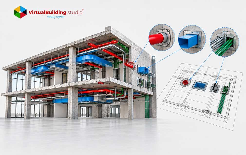
LOD 350 requires every penetration to be modeled at rough opening dimensions, not as a placeholder circle. That means the sleeve material, the firestopping assembly, and the annular space specified by the testing standard all need to be in the model before the structural team signs off on the deck.
Floor penetrations are the most common case. Cast-in-place pipe sleeves need to account for the carrier pipe, thermal insulation, and the annular space required by code, and the model has to track clearance from structural reinforcement to keep minimum concrete cover intact. Pre pour sleeve drawings in BIM pulls this geometry directly from the model to confirm that the concrete web between clustered sleeves in a mechanical chase still meets the structural engineer's requirements before anyone pours.
Wall penetrations carry a different set of constraints. Where MEP systems cross a fire-resistance-rated assembly, the detail has to match a tested firestop system under UL 1479 or ASTM E814, including the exact annular space the manufacturer's listing allows. Three performance metrics drive this coordination:
- F-Rating indicates how long, in hours, the assembly holds back flame.
- T-Rating says how long before the unexposed side rises 325°F above ambient temperature.
- L-Rating specifies how much air and smoke the assembly lets through, measured in CFM per square foot.
- Sound Transmission Class (STC) ratings matter here too. An unsealed 1-inch gap around a duct penetration can drop a wall assembly's acoustic performance by 10 STC points, undoing the isolation the design called for.
Below-grade penetrations add a waterproofing requirement on top of the structural one. Foundation walls and grade beams need wall pipes with integral water stops, sized to leave at least a 1-inch annular clear space for the mechanical seal. Coordinating these thimbles in the model before the pour keeps them clear of the heavy shear stirrups and tensile reinforcement concentrated in grade beams.
Revit Sleeve Coordination for MEP Hangers, Struts, and Structural Anchors
A sleeve that clears the structural model is only half the coordination problem. The hanger, strut, or anchor that supports the pipe or duct running through it needs the same scrutiny, since a Revit MEP hanger clash discovered in the field costs just as much time as a missed plumbing sleeve coordination.
Multi-tier pipe and duct runs supported on trapeze hangers need documented clearance envelopes, both horizontal and vertical. The model has to confirm that unistrut channels and threaded rods clear suspended ceilings, structural steel fireproofing, and any adjacent mechanical system. Coordination teams build rule-based spacing between hangers that accounts for structural capacity and the physical room a crew needs to install them with hand tools.
Anchor inserts carry their own clash risk, separate from the hanger assembly above them. Concrete deck inserts and wedge anchors that receive hanger rods are governed by ACI 318 Chapter 17, which sets embedment depth, edge distance, and anchor-to-anchor spacing to prevent the concrete around the anchor from breaking out under load. An automated interference check between the anchor's 3D volume and the top and bottom mats of slab reinforcement confirms the anchor lands between rebar spans instead of on top of them.
Seismic bracing adds a layer most coordination efforts miss until late in the process. ASCE 7-22 Chapter 13 sets bracing requirements for non-structural components, applying to mechanical equipment over 400 lbs or any life-safety system with an importance factor of 1.5. Under Section 13.6, ductwork over 6 square feet in cross section, or heavier than 17 lbs per linear foot, needs seismic restraint. Modeling the geometric envelope for these 45-degree struts, including the 3-inch clearance required around fire sprinkler drops, keeps the restraint system from becoming its own clash during an event it is meant to survive.
Pre-Pour Sleeve Drawings BIM: Creating Field-Ready MEP Sleeve Shop Drawings
A clash-free model does not help a crew on the deck unless it gets translated into dimensions they can measure from. That translation step, not the modeling itself, is where coordination work becomes installation-ready MEP shop drawings.
Dimensioning starts from fixed points the field already trusts. Every sleeve, block-out, and anchor insert on an LOD 400 drawing is annotated with its distance from the nearest structural column gridline, along with inner and outer diameter, material, top-of-sleeve elevation, and the spacing needed to satisfy UL 1479 annular space rules and ACI 318 web thickness limits. A crew working off these drawings is measuring from a column they can see, not guessing at a dimension buried in a 2D plan note.
The more direct path skips manual measurement altogether. BIM software generates a layout point at the exact center of every modeled sleeve and anchor. That data exports as a .CSV or .DXF file loaded directly into a Robotic Total Station (RTS), such as a Trimble or Leica system. A single operator running an RTS can lay out 600 to 800 points a day at a tolerance of ±2 mm to ±3 mm, compared with roughly 150 points a day and a ±5 mm to ±10 mm margin of error using a tape measure. For a contractor laying out hundreds of sleeves across several floors, that gap in speed and accuracy determines whether the schedule holds.
MEP Sleeve Coordination QA/QC Checklist Before Concrete Pouring
The verification step before sign-off needs to be as disciplined as the modeling that preceded it, or pre pour sleeve drawings in BIM become a formality instead of a safeguard. Tracking each clash to closure through the BIM Collaboration Format (BCF) gives the project team a record of what was checked and who approved it, rather than a verbal confirmation that something looked fine.
Before a pre-pour concrete deck is released, the coordination team should confirm:
Sleeve dimensions
Inner diameter matches the carrier pipe outside diameter plus the tested annular space from UL 1479 or ASTM E814.
Rebar edge distance
Anchors and sleeves clear reinforcement at the ACI 318 minimum of three diameters on center.
PT tendon clearance
Sleeve locations sit outside the 3D parabolic sweep of every post-tension tendon.
Hanger and anchor clearance
Trapeze envelopes and anchor inserts are checked against rebar mats to rule out a Revit MEP hanger clash before anchors are set.
Seismic clearance
Strut envelopes maintain the 3-inch minimum clearance ASCE 7-22 Section 13.6 requires around sprinkler drops.
RTS layout accuracy
Exported CSV or DXF data is calibrated against physical site control points before field staking begins.
Working through this list before the pour, rather than after, is what keeps the coordination effort from becoming a paperwork exercise that nobody checks against the actual deck.
Conclusion
Field decisions about sleeve placement do not disappear under this approach, they just move earlier, where a wrong location costs a model update instead of a diamond blade and a structural engineer's sign-off. Under MEP sleeve drawing coordination, every code requirement, from ACI 318 spacing to ASCE 7-22 bracing, is checked against the model instead of guessed at on the deck. The payoff shows up during rough-in: sleeves cast where the RTS layout points were set, hangers and anchors that clear rebar on the first try, and firestop details that match their UL listing without a change order.
For a project team building to LOD 350 or 400, the practical next step is procedural. Lock the Revit sleeve coordination checklist into the pre-pour sign-off process, the same way clash detection services is already locked into design review, so the deck gets poured once.

Eliminate costly field core drilling before your next pour