+1 (409) 800-6601
 contact@virtualbuildingstudio.com
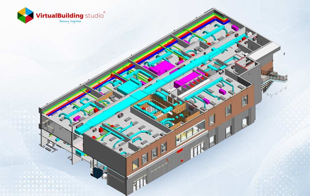
A detailed MEP BIM model can still fail on the jobsite. Project managers open a model, see dense geometry, and assume the design is ready to build. Field crews find something different. Ducts collide with structural beams. Pipes lack the slope needed for drainage. Hangers have no real attachment point. Model detail alone, measured only in visual density, does not equal construction readiness.
MEP systems account, for 40% to 60% of total construction costs in commercial buildings.That figure climbs to 65% in hospitals and lab facilities. Coordination failures across trades feed an estimated $31.3 billion lost annually to construction reworkin the United States.
True readiness requires four things working together: model usability, spatial coordination, installation feasibility, and automated documentation. When any one is missing, field teams stop work and file RFIs. Then they wait for fixes that should have happened during design.
What is a Construction-Ready MEP Model?
A construction-ready BIM model represents building systems at exact physical tolerances. It includes verified manufacturer data, trade-specific assembly logistics, and code-compliant clearances. Design-intent models validate engineering calculations and general routing, but they stop short of a true MEP model for construction. A construction-ready MEP construction model goes further. It acts as a digital twin of the physical build, capable of driving fabrication, procurement, and layout without field changes.
Trade subcontractors judge readiness by a different standard than design engineers. A model qualifies as ready only when it resolves every spatial conflict with the surrounding architecture and structure. Research shows mechanical trades lead direct spatial coordination on 51% of projects, compared to 27% for general contractors. Contractors who carry the installation risk are the ones pushing models toward buildable accuracy. A weak BIM model for contractors becomes their problem on site.
A usable BIM model for contractors delivers four core capabilities:
- Geometric fidelity - Manufacturer content showing real outer dimensions, joint mechanics, and fitting radii.
- Clearance integration - Insulation envelopes, valve rotation space, and code clearances built directly into the 3D geometry.
- Structural realism - Hangers, trapezes and seismic restraints modeled as per actual slabs and framing.
- Direct deliverables - Shop drawings, spool sheets, field layout coordinates and bills of materials generated directly from the model.
When these criteria are met, field teams shift from solving problems reactively to assembling proactively. A 2-inch spatial error that goes undetected can cost $15,000 to $25,000 in labor, material waste and delay.
Design MEP Model vs. Construction-Ready MEP Model
Design engineers build models to prove a system meets code and performance targets. Trade contractors and VDC teams build the MEP coordination model to dictate manufacturing, shipping, and assembly. The differences show up across every technical category.
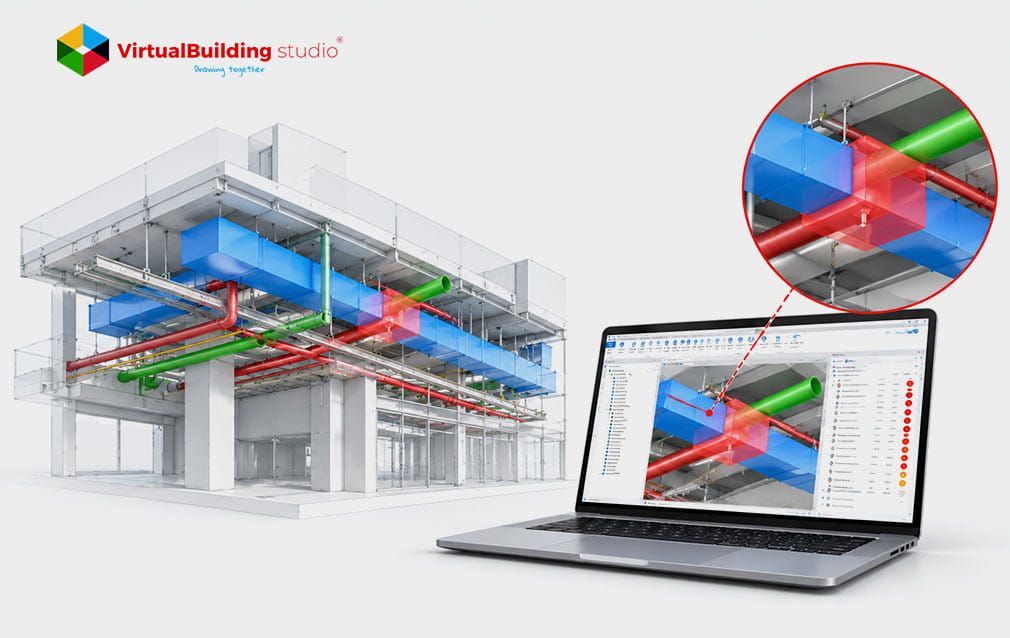
A design model can look complete while hiding real risk. An engineer may route a 12-inch chilled water line flat through a plenum. Once insulation, coupling flanges, and drop rods are added, that same line needs more room than the drawing shows. Left unresolved, this triggers physical collisions, stalled crews, and RFIs during installation.
7 Key Requirements of a Construction-Ready MEP BIM Model
Meeting construction readiness means satisfying seven distinct technical requirements. Each one closes a specific gap between design intent and field reality, and together they define real MEP constructability.
Accurate MEP Geometry and System Representation
Generic parametric parts almost never match what actually ships to site. A construction-ready model replaces them with manufacturer-exact or fabrication-database geometry.
- True fitting radii - Elbows, taps, and reducers follow SMACNA, Victaulic, or ASME standards so centerlines stay predictable.
- Insulation jackets - Modeled as physical geometry, not invisible parameters, since insulation changes effective outer diameter.
- Pitch and slope - Gravity lines carry exact slope values. This keeps a long run from dropping into a structural beam.
- Equipment dimensions - AHUs, chillers, and switchboards are built from approved submittals so connection points match delivered hardware.
Appropriate LOD and Model Information
Readiness is based on the use of the appropriate Level of Development as defined by BIMForum LOD 350 introduces cross trade coordination, including support connections and clearance envelopes. LOD 400 adds fabrication-grade data: cut lengths, spool breaks and sequencing.
Most Revit MEP model teams treat LOD 350 and 400 as the field-ready baseline. Alongside geometry, non-graphic data matters just as much. System codes, voltage ratings, flow rates and manufacturer tags must be embedded in every element. Structured parameter data cuts facility management handover errors by up to 38%.
Complete MEP Coordination
An MEP coordination model resolves spatial conflicts before crews reach the site. Teams assign plenum space using a strict priority order. Gravity drainage comes first, then large ductwork, then hydronic piping. Cable trays and terminal units follow near the ceiling grid. Within that structure, coordination teams resolve three clash types:
- Hard clashes - Two objects physically occupy the same space.
- Soft clashes - An object encroaches on a required clearance or access envelope.
- Workflow clashes - One trade's sequence blocks another trade's later installation.
Structured MEP BIM coordination services cuts field change orders by up to 40% compared to manual review.
Installation-Ready Dimensions and Clearances
A model is not construction-ready if crews cannot safely access what they install. NEC Article 110.26 sets the baseline for electrical working space in the United States.
- Depth - 3 feet minimum for low voltage systems, more for higher voltage with exposed parts on both sides.
- Width - 30 inches or the panel width, whichever is greater, so doors open fully.
- Headroom - 6.5 feet clear, or the equipment height, whichever is greater.
- Dedicated space - No foreign systems, including ductwork or drain lines, within the protected zone above panels.
Mechanical equipment needs its own service clearances too, including coil pull space and accessible valve stems.
Constructability Validation
MEP constructability checks confirm systems can actually be built and secured inside the building envelope. Hangers and trapezes get modeled against real concrete anchors or structural steel, not deck flutes.
Seismic bracing gets checked against adjacent trade systems in high-seismic zones. Sleeves and core-drill points get verified against rebar layouts before concrete gets poured. Large equipment gets a modeled transport path through corridors and shaft openings before it ships.
Construction Documentation
Reliable shop drawings come straight from coordinated geometry, not disconnected 2D linework. A construction-ready Revit MEP model supports bi-directional associativity, so any model change updates every plan, section, and schedule automatically.
Dimensions tie to centerlines and strucstural grid lines instead of static text. Trade contractors extract wall sleeves, hanger points, and equipment pad details from these coordinated views. This turns the model into a working MEP shop drawing model.
Fabrication and Shop-Drawing Readiness
The final step moves coordination into off-site manufacturing. An MEP shop drawing model reaches LOD 400 when pipe runs get segmented into spool lengths. Weld and coupling points are defined at each break.
Ductwork carries SMACNA-compliant joint and seam data ready for CNC cutting. Field layout points get embedded for robotic total station use, letting crews locate anchor points with millimeter accuracy. Prefabrication built on this data cuts construction waste by up to 15%.
Meeting these seven requirements is only half the job. Teams still need a structured way to confirm every requirement actually got met before drawings ship.
MEP BIM Quality Control and Model Validation Checklist
Before shop drawings go out, VDC managers run a validation pass. Every technical category gets checked in sequence.
- Model health gets checked first: unlinked references, unresolved warnings and correct project origin points.
- Spatial coordinates get verified against the shared architectural and structural system.
- Geometric fidelity gets checked against manufacturer submittal sizes.
- Insulation gets confirmed as modeled geometry across every required hot or chilled system.
- Electrical clearances get checked against NEC 110.26 minimums.
- Mechanical clearances get checked for coil pull and valve access space. Slope and pitch get checked against required plumbing code gradients.
- Hanger attachments get checked against structural steel or slab deck locations.
- Sleeves get checked against rebar and post-tensioned tendon layouts.
- Data completeness gets checked for full OmniClass tagging and system codes.
Many VDC teams now run this checklist through cloud platforms like PlanRadar or Autodesk Construction Cloud. Teams using cloud-integrated QA platforms cut report generation time by 75%.
A checklist confirms one model is ready. Turning that result into a repeatable outcome across every project takes the right practices.
Best Practices for Creating Construction-Ready MEP Models
Consistent constructability comes from process, not one-time effort. A few practices separate projects that avoid rework from those that do not.
Formalize a BIM Execution Plan
Define the model author and LOD target for every component. Projects with a standardized BEP cut field rework costs by 28%.
Hand modeling to subcontractors early
Trade contractors bring field assembly knowledge that design engineers do not carry. This approach drives over half of successful project coordination efforts.
Filter clash detection intelligently
Rules-based filters separate hard clashes from minor soft clashes. This is core to the MEP BIM coordination process and cuts review time by 60% to 70%.
Standardize naming and parameters
Consistent family names and system codes across trades reduce handover data errors by 38%.
Verify existing conditions with laser scanning
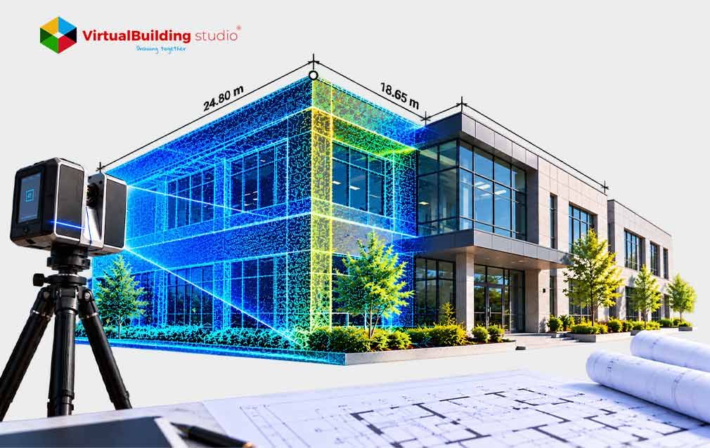
Point cloud data confirms real site geometry before new systems get modeled. This matters most on renovation projects.
Move issue tracking to the cloud
Dynamic platforms replace static PDF clash reports. This approach cuts project delays by up to 30%.
These practices turn constructability into a habit, not a one-time push. Together, they explain exactly what a truly construction-ready MEP model delivers on site.
Conclusion
Moving from a design-intent model to a truly construction-ready BIM model takes more than added geometry. It takes accurate manufacturer data, resolved clearances, structural validation, and documentation that field teams can trust. Design models describe what a system needs to do. A construction-ready MEP BIM model describes exactly how trade teams will build, sequence, and maintain it.
Teams that apply LOD milestones and enforce statutory clearance rules see the payoff directly. Rework costs drop below 5%. Field change orders fall by up to 40%, and project delays shrink by up to 30%.That gap between a model that looks finished and one that is field-ready is where budgets and schedules get protected.

Get A Fully Coordinated, Field-Ready MEP BIM Model Built For Your Project