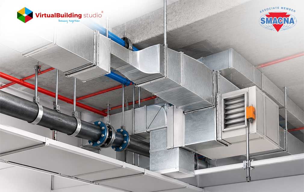
Revit ductwork modeling can successfully help clear each clash check but ultimately not get installed on site. The installer shows up with a pre-manufactured section, a fitting bolt, and a fastening cleat, but there simply isn't enough space for installation of the three items.
It is due to Revit's default centreline routing that results in the generation of a nominal airflow geometry while disregarding the flange profiles, insulation protrusion, and classes of rigidity of the joints. Hence, it results in testing the model that is free from clashes while smaller than the actual prototype to be installed.
The standard that rules in the industry is ANSI/SMACNA 006-2020, which is HVAC Duct Construction Standards: Metal and Flexible, Fourth Edition. This 416-page guide is described as the latest achievement in SMACNA standards for Revit HVAC design and installation. The solution here is to create the step-by-step scheme for project development, which will conform to SMACNA duct standards for Revit installation and which goes from the flanges to Navisworks tests.
The Core Gap: Design-Intent Revit Ducts vs. SMACNA Fabrication Reality
The disparity stems from the product itself. A conventional Revit duct aids in establishing a design: defining the path, system, stated size, and flow. However, fabrication parts have additional information that cannot be captured by the fabrication drawing.
Generic and Fabrication Parts (ITMs)
A generic duct is a uniform body without flanges. In contrast, the coil line produces finite lengths with butt joints, seam, and connector hardware.
Coming back to BIMForum, while an LOD 300 object can be measured by design, an LOD 400 has a higher detail level for the fabrication, constructing, and installing of the object. An LOD 300 model doesn’t imply having built-in joints and connection extensions, as well as tool access.
Fabrication parts contain service, gauge, connector, and insulation data. This is the basis for SMACNA duct standards for manufacturing Revit project work, provided that the audit of the database accordance with SMACNA tables is successfully completed.
The True Size of a Duct
Stretching the measurement to represent the sheet metal, insulation, and the protrusion of flanges as one single number is incorrect since insulation and flanges are actually in the same position. The measurement is to be divided into three general groups:
- Insulated volume: the actual size, plus twice the insulation thickness.
- Space for flanges: the actual size, plus twice the distance of the biggest projection outside the body, such as a flange, a corner, a bolt, or a cleat.
- Working envelope: the joint envelope plus a working space needed to bolt, fold, close, or open a door.
Effects of MEP Coordination
The envelopes fail in different ways, which means that a nominal gap means nothing. Imagine a duct face located 3 inches from a beam and having a 2-inch wrap around it. In this case, its jacket has 1 inch of space to the beam, while an uncovered TDC with a 1.5-inch flange offers it 1.5 inches of clearance.
But that still doesn’t mean that there is a hard clash. This joint will still fail construction if it requires a tool space of 3 inches. If the duct is moved just 1 inch, a collision will occur.
While delivering MEP BIM services, this is the basic principle of BIM duct clearance for HVAC. A hard clash asks whether there is an intersection of geometries. Clearance testing asks whether the clearance achieved in this situation is compliant with project requirements. All clashes should be reported as separate issues, i.e., with regard to the body, insulation, flange fittings, or tool zone against the beam.
Every joint type needs different projection and space requirements, hence the classifications come next.
Understanding SMACNA Joint & Flange Classifications in 3D BIM
There is a dependence between the envelopes referred to above and their junctions, with SMACNA's T-25a and T-25b naming showing the equivalence of TDC and TDF junctions. The name of a connector does not make it fit for a particular purpose. Such components as pressure class, size, gauge, type of reinforcement, and seal class come into play as well, and influence the fact that the assembly is implemented or not.
Commonly Used Flange Designs Modeled in Revit
- TDC / TDF: This kind of design is made of sheet and comprises 1.375 to 1.5-inch projection and 3 inches reserved for corner bolt and cleat tool. These measurements are preliminary, as what is used as the item under assembly determines the precise profile.
- Slip & Drive (S&D): The type of duct with low pressure, within ±2 in. wg limits, as allowed by the schedule. The standing slip has 0.5 inches of projection, while the drive cleat is projected by 2 inches.
- Four-bolt duct mate: Applicable for intermediate to high pressure, according to the system rating, with the projection being around 1.5 inches and 3.5 inches used for bolt placement and the impact wrench. Actual figures are beyond the baseline values.
- Companion angles and welded flanges: High-pressure and industrial runs. Projection runs 1.5 to 2.0 inches by angle leg, and 4.0 inches covers drift pin and ratchet access. Bolt heads, washers, and nuts belong in the envelope.
For Revit duct flange modeling, store projection and tool clearance as separate shared parameters, such as Flange Projection and Tool_Clearance_Side_A.
Those joint envelopes now need rules for what they may touch.
Establishing Mandatory Duct Clearance Rules in Revit
While joint ports might lead to clearance rules, it must be first clarified what "mandatory" means. SMACNA is responsible for duct systems building and setting no uniform distance to other systems. Thus, mandatory refers to obligations imposed by a contract, code, a manufacturer, or project coordination matrix.
Space Cravings and Clearance from Structural Systems
When it comes to structures, that's where the regulations hit the hardest as hangers, insulation, and flanges all demand their own space. 2-3 inch gap might be a solid basepoint but it's not a rule for either SMACNA or IBC.
- Use the distance of two inches in case of straight ducts and three inches in joints and hangers.
- It should depend on position: top space might depend on hangers, and side distance is defined by TDC TDF flanges.
- There should be the Structure_Movement_Allowance parameter for each zone.
- Duct shouldn't even touch fireproofing. Contact restricts insulation and hangers so fireproofing thickness should be incorporated into the construction.
Clearance to Adjacent MEP Trades
Both pipes and conduits take advantage of the available ceiling area, but both have different insulation systems or access provisions.
- Ducts and pipes: Maintain at least 3 inches of space between finished jackets and at least 4 inches at fittings, supports, steam pipes, and vapor barrier seals.
- Cable tray: Use the common 6-inch separation, which is a common good practice in cases like this, even though it has no basis in the NEC.
- Panels: The NEC 110.26 gives a minimum working space width of 30 inches and 6.5 feet in height. The depth is defined in Table 110.26(A)(1) and usually takes on the values of 36 inches. Make sure to create working spaces in panel designs so that ducts will never be installed there.
Access Clearance for In-Line Accessories: SMACNA & NFPA Requirements
Accessories have to be accessible for many years after their installation.
- Fire and smoke dampers: The standard operating procedure 90A stipulates a 12-in. x 12-in. access panel or removable duct segment. This applies to dampers with fusible links or internal actuators. Many owners prefer panels measuring 18 in. square; compliant edition and AHJ may dictate sizes. NFPA requires that fire dampers should be inspected and tested one year after installation and every four years (or six in hospitals) after that.
- Access panels and filter racks: Create three categories in a family of items: accessory, swinging or removable section, and working section with a tool zone. Keep the solids under the Clearance subcategory for coordination view, but not for construction documents.
Standards matter only if the model is implemented, so now we turn to the implementation.
Step-by-Step: Configuring SMACNA Standards in Revit HVAC & Fabrication CADmep
Four steps put those rules into the model.
Load Specification-Driven Duct Services
Initiate the mechanical BIM modeling workflow with the pressure-class and service matrix extracted from the contract documents. The specifications may be set up in CADmep or CAMduct in a way that will ensure that the duct size leads to the choice of gauge, connector, seam, and straight length. It is worth mentioning that even when a service is loaded, that does not mean that Revit will apply SMACNA on its own. Automation is actual only to the extent allowable by the tables’ accuracy that have been programmed into the database.
In Revit, load the production configuration and HVAC profile and convert the duct in the design through the bounded zones. Those who will work with generic duct should label the result as an LOD 300/350 approximation.
Incorporate Insulation Thickness in Routing Rules
Model the external insulation in the Revit environment. It is possible to carry out the insulation of the entire duct system or its individual pieces with the thickness defined in the model. It is necessary to create a QA parameter, Finished_Width = Nominal_Width + 2 × Insulation_Thickness in the system.
Apply Standard Sheet Metal Segment Lengths
Before making the final adjustments, it is recommended to replace continuous runs with lengths that match those used in the shop. The length of 5 feet or 59 inches is a configuration specific to the manufacturer and not a generalized SMACNA regulation. For Standard_Straight_Length, you need to verify every joint as follows:
- Avoid making any connectors when it is impossible to reach corner bolts or drives.
- Avoid making any joints inside rated walls unless otherwise allowed by the assembly.
Create Clearance Zones via Sub-Categories
Put transparent solids into the families of equipment and accessories in the subcategory of Clearance. Keep installation clearance separate from maintenance clearance, so as not to lose access in temporary situations. Add a collar family for joint modeling that uses direction solids to provide access for bolts, cleats, and tools. Use the Revit system of duct flanges modeling to help coordinators to find out the actual amount of tool space. Run a pilot and check 10 objects before creating a federated model.
Navisworks Coordination Setup: Checking Flanges and Clearances
Teams export those clearance solids to Navisworks and choose test types and tolerances.
Hard Clash vs. Soft Clearance Rules
Autodesk has provided a classification of four different test types categorized as Hard, Hard (Conservative), Clearance and Duplicate. The Clearance test measures the distance at which any object overlaps the other. It is different from the soft clash described by Autodesk about moving geometry with animation.
Hard tolerance at an inch does not imply having a reservation of one inch because it may provide no clearance for penetrations above one inch. Configure tests this way:
- Duct, insulation and flange vs. structure: Hard, with near zero tolerance.
- Joint installation space: Clearance, with a space of 2 to 4 inches according to the joint rule.
- Maintenance and code zones: Hard against clearance geometry that is defined, with zero as the tolerance.
- General proximity: Clearance according to matrix values, for instance, 3 inches.
Eliminating False Positives
Noise is obscuring real problems, therefore it is a good idea to create separate search groups for duct metals, insulation, flanges, hangers, structures and fireproofing. Use the ignore rules with care, as insulation in contact with the previously applied insulation is evaluated only if both have been installed with full thickness. Group the results by station or zone, as one problem will create many clash triangles.
Creating a Dedicated "SMACNA Verification" Search Set
Create a search set called SMACNA_Verification based on the properties instead of picking something by hand, so that the search set updates along with the model. The search set should include a fabrication service, pressure class, fittings, connectors, hangers, access doors, dampers, and every Clearance_Purpose. The following tests are recommended:
- SMACNA-01: Physical duct assembly comparison versus building and fireproofing
- SMACNA-05: Zones of dampers and access doors comparison versus all other trades
Make sure to document the tolerance, revision, assignor, and explanation of each resolved clash. Having documented everything helps HVAC BIM coordination meetings concentrate on the matter of real installation risks.
Many mistakes come from modeling and can go through all the required tests, which will be discussed in the next chapter.
Common Modeling Mistakes That Cause Jobsite RFIs
Navisworks only tests the contents of the model, resulting in errors that get passed to the field.
- Transition angles: Certain specifications report 30° expanding and 45° contracting, but these should not be universally understood as SMACNA limits. Other variations allow 20° diverging and 30° converging angles instead. Make sure to document the angle policy adopted for your project and also flag any violations that arise.
- Seams and cleats against walls or partitions: A body only test will pass as long as the drive cleat can make contact with the wall. It is better to coordinate joint stations and sides of work rather than nudging centerlines.
- Over-approximately offsetting: The auto-routing mechanism produces series of tiny elbows which fulfill connectivity requirements while bypassing needs for brakes. The throat, seam allowance, and connector should be checked for each fitting, and every non-standard offset must be reviewed once conversion has taken place.
Other issues potentially arise as well:
- One clearance per connection: The mentioned TDC TDF flange clearance uses the same value no matter the size, material and reinforcement of the component.
- Missing corners and bolts: The calculations of the duct for Revit do not account for the corners or bolts.
- Insulation as a text note: HVAC duct clearance checks in BIM cannot test metadata.
SMACNA-associated members deliver MEP BIM modeling services addressing all these challenges so the model aligns properly with duct clearance and duct flange rules.
Conclusion
All errors related to HVAC duct shop drawing production stem from less rigorous testing of geometry than what is installed. Proper SMACNA modeling in Revit minimizes the gap between engineering drawings and economical factory production in the case of compliance being a controlled process. This requires an audited specification, modeled joints and insulation, and separating access from physical geometry. Reliable MEP BIM coordination services ensure proper implementation of SMACNA duct fabrication in Revit and end with a constructability review prior to issuance.
Next, a project coordination matrix should be prepared listing all services, pressure classes, connector families, tool spaces, clearance values and approvers. 2-3 inches from the structure, 3-4 inches from the pipe, and 6 inches from the tray should be treated as tentative. Approval is necessary from engineers, fabricators and AHJ.

Need SMACNA-compliant, installation-ready HVAC models for your next project?