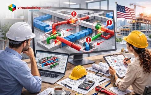
Modern construction projects depend on coordinated building services. MEPF systems support building functionality, occupant comfort, and operational performance. These systems account for nearly 40–60% of total construction costs. This cost share places strong pressure on precise planning and system integration during the design stage. MEP coordination integrates these disciplines within architectural and structural frameworks. Project teams develop coordinated building services before construction begins. This workflow supports the “First Time Right” philosophy. Design teams resolve spatial and system conflicts inside a digital environment. They avoid resolving these issues during on-site installation.
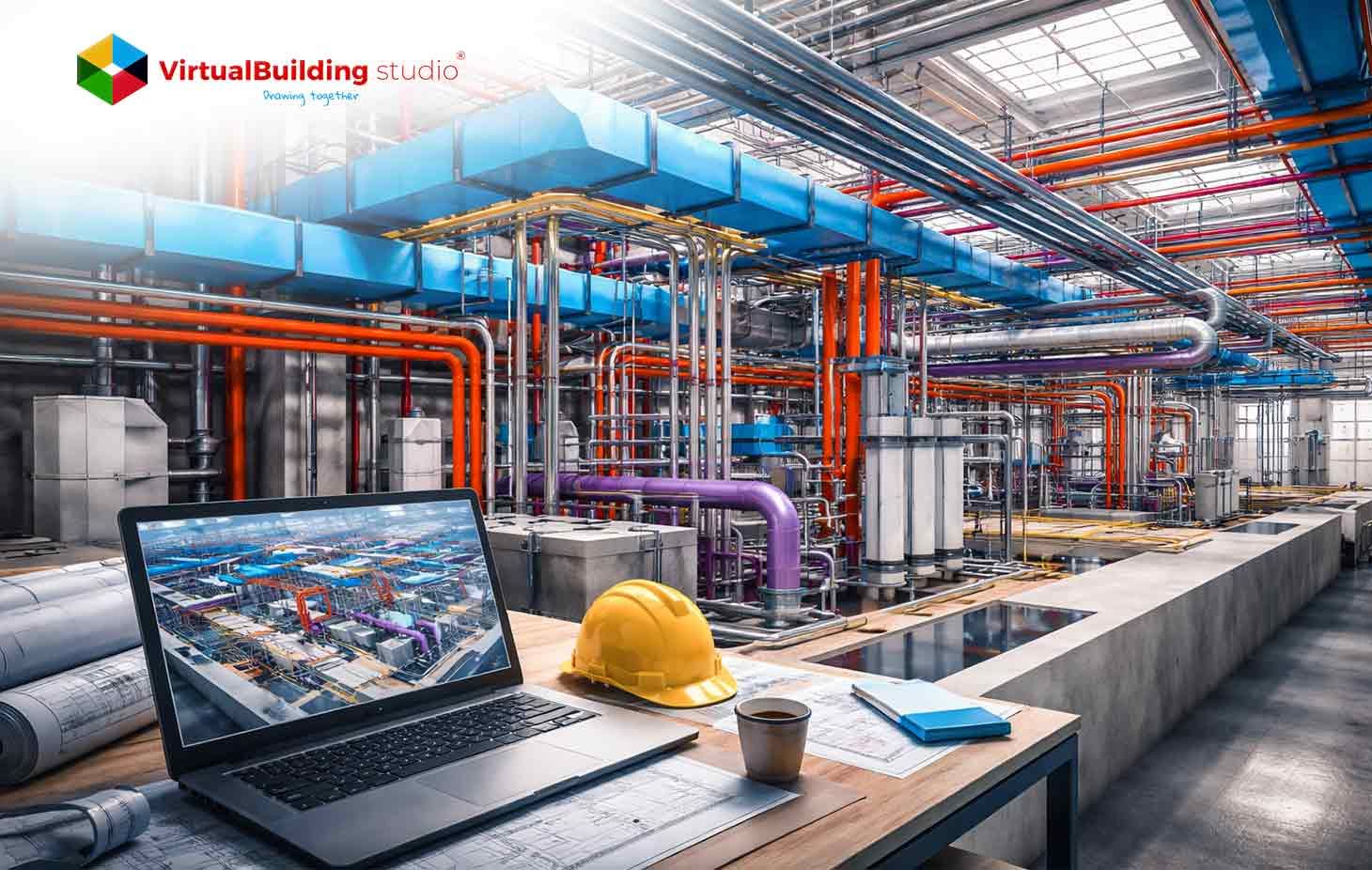
Mechanical systems play a dominant role in this coordination framework. HVAC equipment, ventilation networks, ductwork systems, and mechanical piping occupy large spatial zones. These zones include ceiling plenums, service shafts, and mechanical rooms. This spatial footprint shapes the routing strategy for other building services. Electrical conduits, cable trays, plumbing networks, and fire safety systems are aligned with these mechanical layouts. Accurate mechanical modeling establishes the backbone of MEP coordination. The model provides a clear spatial structure for multidisciplinary design collaboration.
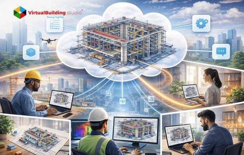
3D BIM Modeling introduces a digital workflow for integrated coordination. BIM platforms allow project teams to create detailed 3D models. Teams simulate system layouts. Teams identify conflicts between disciplines before construction begins. BIM tools like Autodesk Revit, Navisworks, AutoCAD MEP, and MagiCAD support modeling, coordination, and digital collaboration. Teams allocate space for building services through this virtual design process. Teams detect coordination issues early. Teams produce coordinated models that guide efficient construction workflows.
What Is Mechanical BIM Modeling in MEP Projects?
Mechanical BIM modelingrepresents the process of creating data-rich 3D digital models of mechanical building systems inside a Building Information Modeling environment. These models contain geometric representation and technical parameters. The parameters describe system performance, airflow capacity, equipment connections, and spatial placement. Mechanical systems regulate indoor environmental conditions. They control heating, ventilation, and air distribution infrastructure. These systems occupy large spatial zones across ceilings, shafts, and mechanical rooms. This footprint establishes the primary spatial framework for coordinated building services in MEP projects.
Mechanical BIM models represent major HVAC equipment and distribution networks such as:
- Air Handling Units
- Chillers and cooling towers
- Boilers and circulation pumps
- HVAC ductwork systems
- Mechanical piping networks
- Diffusers and air distribution terminals
Organizations that deliver Mechanical BIM Modeling Services develop coordinated digital models. These models guide spatial planning and system performance analysis during design development. Engineers use the models for engineering evaluation. Engineers define equipment placement strategies. Engineers perform airflow calculations. Engineers coordinate routing across disciplines. Mechanical models provide visual clarity through parametric components. These components update automatically when design parameters change. Electrical conduits, cable trays, plumbing pipes, and fire protection systems integrate around the mechanical infrastructure inside coordinated BIM environments. This structure forms a foundation for interdisciplinary MEP coordination.
Understanding Project Requirements and BIM Execution Plan (BEP)
Successful MEP coordination starts with clear project planning and defined digital workflows. The BEP acts as the strategy document for BIM implementation. The document outlines how BIM processes guide the project lifecycle. The plan defines collaboration procedures. The plan defines modeling standards and communication protocols. Multiple disciplines operate inside a unified digital environment from early design through construction documentation.
A BEP typically defines the following project parameters:
- Project scope and BIM objectives
- Modeling standards and naming conventions
- Roles and responsibilities for BIM teams
- Software platforms used across disciplines
- Data exchange and model sharing protocols
- Coordination meeting schedules
- Clash detection procedures
This planning stage occurs during early design phases. Project teams review building requirements, spatial constraints, and system integration strategies. Engineers analyze mechanical system layouts during this period. Engineers review equipment zones and routing priorities. These priorities influence the placement of other building services.
Coordination planning continues through the Design Development phase. The process moves toward the Construction Documentation phase. Model accuracy increases over time. Teams perform coordination reviews to validate system placement and spatial alignment. Early planning improves constructability evaluation. Early planning supports installation planning. Teams improve multi trade coordination across the project.
The BIM coordination process includes collaboration among several project participants:
- Architects
- Structural engineers
- MEPF engineers
- General contractors
- BIM managers and coordinators
Project teams collect essential digital inputs before modeling begins. These inputs include architectural models, structural models, design drawings, and site information. Teams align models using common project coordinates. Teams begin coordinated modeling inside a shared BIM environment.
Setting Up Mechanical Systems in Revit for Coordination
Autodesk Revit serves as the primary platform for coordinated mechanical models in BIM-based MEP workflows. The setup process starts with loading a MEP BIM template. The template aligns with company modeling standards. Templates include predefined families. Templates include parameter settings, system classifications, and naming conventions. These settings support consistent model development across project teams. Engineers link architectural and structural models during the early setup stage. This step establishes the spatial framework for coordinated mechanical system modeling.
Precise model alignment affects coordination accuracy. Project teams verify coordinate systems. Teams apply Origin to Origin positioning to align architectural, structural, and MEP models. Engineers define system types after alignment. Engineers define equipment layouts and distribution networks. HVAC duct modeling in Revit forms a key activity. Designers create supply air, return air, and exhaust air networks. These networks distribute conditioned air across the building. Parametric modeling allows system elements to update automatically. Updates occur when engineers adjust duct sizes, equipment capacities, or routing paths.
Key setup tasks during mechanical system modeling include:
- Establishing shared project coordinates
- Linking architectural and structural BIM models
- Configuring system classifications and parameters
- Loading Revit families for HVAC equipment and components
- Defining duct, piping, and equipment systems
- Validating alignment
This structured setup process produces accurate digital representations of mechanical systems. These models support integration with electrical, plumbing, and fire protection services during coordination.
Creating Accurate HVAC, Ductwork, and Piping Models
HVAC systems form the largest and most complex mechanical infrastructure in modern buildings. Engineers model these systems early in the coordination process. Their spatial footprint influences the routing of other building services. The process begins with the placement of major mechanical equipment. Equipment appears in plant rooms, mechanical floors, and rooftop zones. Accurate equipment placement defines system connectivity. This placement forms the base for ductwork and piping distribution across the building.
Engineers develop duct and piping networks after equipment placement. These networks distribute air and thermal energy to building zones. HVAC duct systems deliver conditioned air through supply, return, and exhaust pathways. These systems support ventilation and indoor air quality requirements. Piping systems circulate chilled water, hot water, and refrigerant between equipment and terminal units. Designers evaluate ceiling plenum spaces during modeling. Designers review structural beam clearances and shaft dimensions. These checks maintain coordinated system routing across floor levels and service corridors.
Mechanical modeling includes the following HVAC and piping components
- Condensate drainage pipelines
- Refrigerant piping networks
- Air handling units and cooling towers
- Chilled water and hot water piping systems
- Supply air, return air and exhaust duct networks
- Ventilation ducts and air distribution terminals
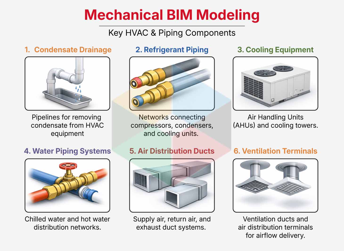
Accurate BIM models include insulation thickness, airflow direction, duct fittings, and pipe connections. These parameters define system performance. Engineers evaluate equipment maintenance zones. Engineers review structural clearances and ceiling space limitations. Data-rich BIM models support airflow analysis. These models support energy performance evaluation and HVAC load calculations. Detailed mechanical models also support prefabrication workflows. Contractors produce duct segments and pipe spools using fabrication-level model data. This approach supports faster installation and improved construction efficiency.
Integrating Mechanical Models with Electrical and Plumbing Systems
Mechanical models act as the spatial reference for other building services inside coordinated BIM environments. Engineers incorporate electrical and plumbing networks after mechanical systems reach coordination readiness. Mechanical equipment, ductwork, and piping appear first. Engineers add electrical and plumbing systems into the shared model afterward. This stage connects multiple disciplines inside a federated digital environment. Architectural, structural, and building service systems coexist inside a unified model structure.
Mechanical routing defines spatial priorities. HVAC ducts require larger clearances than other services. Engineers position electrical conduits, cable trays, and plumbing pipelines around mechanical infrastructure. This placement maintains efficient routing paths. Organizations that deliver MEP BIM Modeling Services support this stage through coordinated discipline models. Teams use centralized platforms for model management. These platforms maintain version control and collaboration across project teams. Accurate integration improves installation planning. The process improves spatial alignment and equipment accessibility across the building lifecycle.
The federated coordination model generally includes the following building service components:
- Electrical panels- switchboards and transformers
- Cable trays and electrical conduit networks
- Plumbing supply and sanitary drainage systems
- Pumps, storage tanks and filtration equipment
- Fire sprinkler pumps and fire protection pipelines
- Smoke curtains and fire shutter mechanisms
These systems interact inside high-density coordination zones. These zones include ceiling plenums, mechanical rooms, and vertical service shafts. Engineers review these areas carefully. Teams maintain sufficient clearance between building services and structural components.
The MEP BIM integration process merges discipline-specific models inside a coordinated digital environment. Teams analyze spatial relationships across building services. Engineers review routing conflicts during coordination meetings. Engineers check equipment access zones and installation sequences. This workflow allows teams to refine system placement. Teams maintain proper routing hierarchies. Teams deliver a coordinated BIM model that supports efficient construction and long-term facility operation.
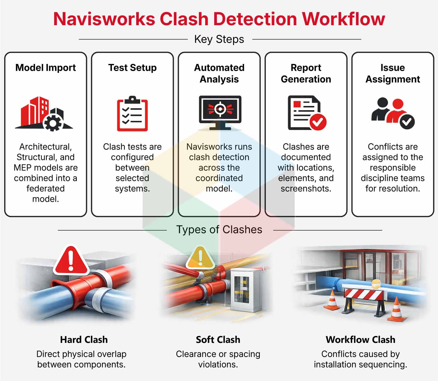
Clash Detection and Coordination Using Navisworks
Clash detection forms a critical stage in BIM-based MEP coordination workflows. Engineers combine discipline models after mechanical, electrical, plumbing, and structural models reach coordination readiness. Teams use Autodesk Navisworks for this process. The software creates a federated coordination model. Experts analyze spatial relationships between building systems inside this environment. Teams identify conflicts before construction begins. MEP BIM models often reveal routing conflicts. These conflicts appear between ducts, structural beams, electrical conduits, and plumbing pipelines in dense service zones.
Engineers run automated clash analysis to detect spatial conflicts. These conflicts can disrupt installation workflows during construction. Coordination teams analyze these issues. Specialists who deliver MEP Clash Detection Services review the conflicts in detail. Engineers refine system routing. Engineers maintain proper clearances between building components. Early conflict detection improves installation planning. The process improves project reliability. Teams conduct structured coordination meetings to review design adjustments and routing solutions.
The Navisworks clash detection workflow includes the following steps:
- Import architectural, structural, and MEP discipline models
- Configure clash detection tests between selected systems
- Run automated clash analysis
- Generate clash detection reports
- Assign issues to responsible discipline teams
- Clash detection identifies several types of system conflicts:
- Hard clashes involving direct physical overlap between components
- Soft clashes involving clearance violations
- Workflow clashes related to installation sequencing
Experience from BIM coordination projects shows clear patterns. Most clashes occur between plumbing and structural elements. Conflicts between mechanical systems and structural components appear next.
Clash reports generated in Navisworks contain detailed coordination data. The reports include element identification numbers. The reports include clash locations, screenshots, and responsible disciplines. Project teams review these reports during coordination meetings. Teams determine routing adjustments. Engineers update discipline models in Revit. Engineers export updated models to Navisworks for validation. Resolved clashes appear as yellow indicators in the model. Newly detected conflicts appear in red. Teams track issue resolution through this visual system across the coordination cycle.
Shop Drawings and Fabrication-Level Detailing from BIM Models
Engineers move the federated BIM model into a fabrication-ready digital resource after coordination finishes. The model supports construction documentation. Engineers extract installation-level details directly from coordinated models. Contractors and fabricators use these details to produce shop drawings. These drawings show mechanical systems with accurate geometry, equipment placement, and routing paths. The coordinated model already reflects building services. Installation documentation aligns closely with field conditions. This alignment supports efficient construction planning.
Fabrication-level BIM models contain detailed information about component dimensions, fittings, supports, and insulation allowances. Contractors use these details to prepare manufacturing outputs for mechanical assemblies before site installation begins. Fabricators connect digital models with specialized fabrication software in many cases. The software generates manufacturing instructions. This digital workflow improves production accuracy. The workflow maintains consistent installation standards across the project.
Fabrication-ready BIM outputs commonly include:
- Mechanical spool drawings for ductwork and piping assemblies
- Equipment connection layouts and installation diagrams
- Assembly drawings for prefabricated mechanical components
- Hanger and support system layouts
- Insulation allowances and fabrication fittings
Mechanical contractors manufacture system components in controlled production environments through prefabrication strategies. Offsite fabrication increases installation accuracy. Offsite fabrication improves construction planning. The process supports faster system assembly after materials arrive on site.
Organizations that deliver MEP Shop Drawing Services convert coordinated BIM models into installation documentation for contractors and subcontractors. These drawings communicate exact component dimensions, routing paths, and assembly sequences required for construction. Fabrication drawings from coordinated BIM models align mechanical components with building structures and adjacent services. Installation teams perform construction activities with higher precision. Teams reduce material waste.
Quality Control and Final Model Delivery for Construction
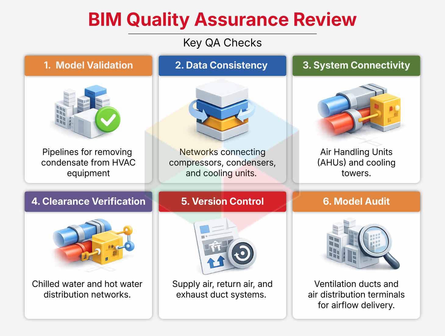
Quality control acts as the final validation stage before BIM models move into construction deliverables. Engineers conduct detailed reviews of coordinated models during this stage. Engineers confirm system accuracy, spatial alignment, and data consistency across disciplines. Reviews verify correct integration of mechanical systems with architectural layouts, structural components, and other building services. Effective Mechanical BIM coordination during this phase supports construction readiness. The process improves installation workflow reliability.
Project teams perform structured QA/QC procedures to confirm that every model element follows project standards and coordination requirements. Engineers review system connectivity. Engineers check routing accuracy and clearance zones in high-density service areas such as ceiling plenums and mechanical rooms. Model audits verify equipment placement. Audits verify service routes against design specifications and industry standards. Teams deliver models that represent accurate digital versions of future building systems through systematic reviews.
Quality assurance reviews usually include the following checks:
- Model validation and geometry accuracy
- Data consistency across discipline models
- Verification of system connectivity and routing
- Clearance validation for equipment and maintenance zones
- Version control and model revision tracking
- Model audits and documentation reviews
Industry standards such as SMACNA and ASHRAE guide mechanical system modeling and validation during these reviews. Engineers apply these standards during evaluation. Engineers verify airflow requirements, duct design parameters, and mechanical system performance inside the BIM environment.
Project teams prepare final BIM deliverables for construction teams after quality control reviews finish. Deliverables usually include a coordinated BIM model, clash-free MEP model, shop drawings, and fabrication documentation. The final model may also contain asset information for facility management systems. Equipment specifications, warranty records, maintenance schedules, and asset identification data become part of the digital building record. This information supports long-term building operations and maintenance.
Conclusion
Mechanical BIM modeling forms the foundation of coordinated building services in modern construction projects. Accurate mechanical models guide spatial planning. The models support integration of electrical, plumbing, and fire protection systems. Engineers evaluate system layouts in a digital environment through BIM-driven workflows.
Engineers identify conflicts before construction begins. Early clash detection improves design clarity. Coordinated routing strategies support installation planning. Detailed models support efficient construction workflows. These digital processes improve collaboration between BIM stakeholders.
Coordinated BIM environments allow experts to simulate building systems before physical construction begins. Tools such as AutoCAD, Revit, and MagiCAD support interdisciplinary collaboration through shared digital models and coordination platforms. Teams analyze building services inside federated models. Teams improve design accuracy. Teams reduce material waste. Teams shorten construction schedules.
BIM-driven mechanical coordination guides efficient design and construction workflows as building projects increase in complexity. Accurate digital models support better project outcomes. These models support improved installation efficiency. High-performance buildings benefit throughout their operational life cycle.