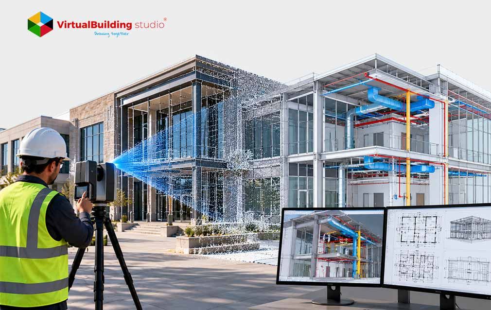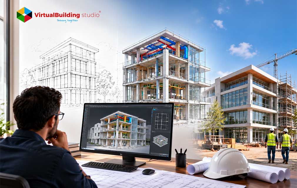
Most renovation projects start with drawings that no longer match the building. Walls have been moved, ducts rerouted, and some original sheets lost. Laser scanning helps teams close that gap by recording the building as it stands today. Teams get millions of measured points, but those points are not yet a model.
That second gap is where projects stall. Teams want to convert point cloud to 3D model geometry inside AutoCAD, and many expect a one-click button. AutoCAD offers no such button. It does let you attach scan data and model against it, which works well with the right preparation.
That preparation starts with understanding what a point cloud actually holds.
What Is a Point Cloud?
A point cloud is the raw record behind a scan: a set of measured XYZ coordinates on real surfaces. Teams capture it with laser scanners, mobile LiDAR or photogrammetry. Each point can also carry RGB color and intensity, which shows how strongly a surface reflected the laser.
Those extras make the cloud readable, but they do not make it a model. Nobody can select a "wall" inside it, because it contains only dots.
Formats matter next. Autodesk workflows mostly use RCP or RCS files after processing in ReCap Pro. E57 is the vendor-neutral option, backed by an ASTM standard, and teams also use LAS/LAZ and PLY.
Scan quality starts in the field. Choosing a 3D scanner for CAD modeling comes down to the accuracy and coverage your deliverable needs. That link between raw evidence and a usable deliverable raises the obvious next question.
Can AutoCAD Convert a Point Cloud to a 3D Model?
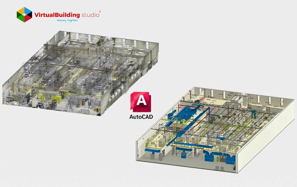
The short answer is no, not at least automatically. AutoCAD handles a point cloud like any external reference. You attach it, snap to it and draw against it, but you create every element yourself.
Four deliverables sound alike here, but they behave very differently:
- Point cloud: measured dots, with no surfaces or objects
- Mesh: a skin of triangles over the dots, useful for visuals
- 3D CAD solid: geometry you draw, like an extruded wall
- Parametric BIM model: walls, doors and ducts that carry data
You can work with the first three in AutoCAD. The fourth needs a BIM platform, so a full laser scan to BIM workflow usually moves into Revit.
That makes the honest framing "point cloud assisted 3D modeling." Users on Autodesk forums keep raising the same limits: registration, cleanup, hardware and manual interpretation. Teams can't fix those with software alone, so preparation decides how smoothly the work goes.
What You Need Before You Start
Teams that prepare before opening AutoCAD get far better results from that manual route. Preparation covers three areas.
Inputs
Your inputs define what the model is for:
- A registered, cleaned scan with clear project coordinates
- A written purpose, such as a 2D as-built plan or renovation model
- A scope listing disciplines, exclusions, elements, formats and approvals
Software
Those inputs then decide your software:
- Full AutoCAD to attach the cloud and build geometry
- Autodesk ReCap Pro to import, register and organize scans
- Revit, Civil 3D or Navisworks for BIM, terrain or clash checks
Ground Rules
Even with the right software, one question stays open: who approves what? Agree on model uses, responsibilities and tolerances before anyone draws a line. Teams can use the BIM Forum LOD Specification and AIA digital data exhibits for this. NBIMS-US Version 4 also gives US teams a lifecycle framework for these decisions.
With those pieces in place, you can start modeling.
Step-by-Step: How to Convert Point Cloud to 3D Model in AutoCAD
That preparation now turns into a sequence of eight steps. Each step depends on the one before it.
1. Plan Capture and Deliverables
Planning sets the targets later steps to check against. Agree on coordinates, coverage, accuracy, model uses, formats and tolerances, and record how you will verify each element.
2. Register and Clean the Scan Data
Registration means joining individual scans into one aligned cloud. Register them in ReCap Pro or your vendor's software using survey control, targets or cloud-to-cloud matching. Then review the registration report, remove noise, crop unused areas, and keep a master copy.
3. Create an AutoCAD-Ready Reference
Clean data then needs the right package for AutoCAD. Export an RCP or RCS file from Autodesk ReCap Pro, and keep the project origin under control.
4. Attach the Point Cloud in AutoCAD
This step is where you start working with point clouds in AutoCAD directly. Use Attach on the Insert tab or type POINTCLOUDATTACH. Confirm insertion point, scale and rotation, then clip the cloud to your work area.
5. Inspect in Sections
Before drawing, study the cloud in plan, elevation and section views. That habit helps you separate real surfaces from gaps and noise.
6. Build CAD Geometry
Inspection tells you what to draw, and this step is the drawing. Trace 2D polylines first, then turn them into solids with EXTRUDE, PRESSPULL and LOFT. This 2D to 3D CAD conversion approach lets you tie every solid to a measured profile.
7. Validate as You Go
Checking only at the end lets errors pile up. Overlay the model on the cloud in several views, and flag uncertain areas instead of modeling them as fact.
8. Deliver with Provenance
A finished as-built model from point cloud data needs a paper trail. Issue the DWG with scope, exclusions, coordinate system, tolerances, QA record and revision date.
These steps get you a model. A few habits decide whether it holds up.
Best Practices for Accurate Point Cloud to 3D Modeling
Those habits start from one idea: teams agree on accuracy instead of assuming it. Four practices help set that target.
Define "Fit for Purpose" Accuracy
Teams have to weigh scanner precision, registration error, point spacing, line of sight, and modeler judgment. So, skip claims like "accurate to X mm" unless you state the scanner, registration result and tolerance.
Use an Element-by-Element Specification
A project-wide target still leaves individual elements undefined. Pair the LOD Specification with a matrix listing each element's geometry, tolerance, intended use and owner.
Use LOD Carefully
The LOD scale itself needs care. The 2025 BIMForum LOD Specification added LOD 250 as optional intermediate level. Early coordination and estimating are appropriate, but fabrication and as-built certification are not approved.
Build a QA/QC Loop
- Good point cloud modeling depends on repeat checks:
- Check registration before modeling
- Validate key dimensions against field checks
- Review plans and sections, not just 3D views
- Record deviations and hidden zones
- Get tolerance sign-off before final issue
Some difficulties appear on just about every project, even with these behaviors.
Common Challenges When Converting Point Clouds to 3D Models
QA habits are greatest when you know what to look for. Five challenges come up again and again.
Automatic-Conversion Expectations
Clients see a dense, colorful cloud and assume the model is nearly done. Someone still decides what counts as a wall face, duct or pipe. Even the best point cloud to BIM software needs a professional reviewing its output.
Large-File Performance
Teams working with dense clouds tend to hit slow AutoCAD sessions. Crop work zones, lower display density, and store data on SSDs. Some firms hand this load to scan to CAD drafting services instead.
Registration Errors
A cloud can look right and still be misaligned with project control. Review registration residuals (leftover alignment errors) and run independent checks before trusting it.
Hidden Conditions
Teams only capture what the scanner can see. Label any geometry you infer behind ceilings or equipment, and plan site visits where gaps matter.
False Precision
People reading a highly detailed model assume more confidence than the scan supports. Skip modeling tiny details just because they look impressive.
Some of these challenges get easier with the right tools.
Automation Tools and Plugins for AutoCAD
Tools help with those performance and cleanup challenges, and contractors are paying attention.
In AGC's 2025 Construction Outlook survey, 44% of responding firms planned to increase AI investment in 2025.
That interest is real, but teams should not expect any tool to produce reliable parametric BIM alone.
Autodesk ReCap Pro
ReCap Pro lets teams register, clean and publish clouds for AutoCAD, Revit and Civil 3D. Check current documentation, because Autodesk changes licensing and features between releases.
Autodesk Construction Cloud
Autodesk Construction Cloud lets teams compare scan context with project models during coordination. Teams still define acceptance criteria, ownership and revision control themselves.
Specialist and Open-Source Tools
Specialist tools help with segmentation, meshing, and deviation checks. Choose by data size, accuracy needs and security, not promises of automatic BIM.
Tool choice matters, but the bigger decision is which platform holds the final model.
AutoCAD vs. Revit: Which Is Better for Point Cloud Modeling?
That platform decision usually comes down to AutoCAD or Revit. Both let you attach a point cloud, but they lead to different deliverables:
AutoCAD fits drawing-based records, while Revit fits projects that need coordinated elements and data. That makes Revit the usual home for laser scan to BIM work. The same logic applies to point cloud to BIM for architects, since renovation design depends on parametric walls.
Teams can also run ReCap Pro, AutoCAD and Revit together as one hybrid workflow. In the wider Revit vs AutoCAD debate, teams pick software based on the contracted deliverable.
Whichever platform you choose, the payoff looks different in each discipline.
Point Cloud to 3D Model: AEC Applications
The platform choice shifts depending on who uses the model, and spending on these tools is growing.
The same AGC survey found 26% of firms planned to increase BIM investment, and 26% planned more drone spending.
Architecture and Renovation
Architects use scans for existing-condition plans, sections, and facade studies. Agree early whether walls show finish faces or structural faces. Teams with legacy 2D plans can check them against the scan before any 2D to 3D CAD conversion.
MEP Coordination
MEP teams use scans to spot routing limits in retrofits. Keep scope tight, since teams can't see much behind ceilings.
Structural Work
Engineers check accessible columns, beams, slabs, and openings against the cloud. They still need material testing and engineering judgment.
Surveying, Civil and Infrastructure
In point cloud modeling for surveyors, everything ties back to surveyed control. Civil 3D or GIS tools suit terrain and corridor work better than AutoCAD alone.
Facility Management and Digital Twins
An as-built model from point cloud data lets owners plan space and track assets. Define asset attributes and update duties at the start.
Across these disciplines, the same few decisions keep showing up.
Conclusion
Every decision above comes down to a clean scan, a clear scope, and honest tolerances. AutoCAD won't do the modeling for you, but it lets drafters work against an exact reference. When you convert a point cloud to 3D model geometry this way, the result holds up in construction. Teams short on time can hand-draft to scan to CAD drafting services. Projects that need parametric elements are better served by architectural scan to BIM services in Revit. Start with the deliverable and work backward to the scan.
Your old drawings are already out of date. Don't let your next design start from them. Send us your point cloud and project scope. We'll tell you what to model, to what tolerance, and in which platform.

Don’t Build Your Next Design on Outdated Information, Get Your Point Cloud Modeled