

Data centers house some of the most complex MEP systems found in any building type. Power distribution units operate alongside cooling assemblies within extremely limited physical space. Structured cabling networks run parallel to fire suppression lines. Intense spatial competition arises from this coexistence. Data centers demand continuous uptime at all times. A minor coordination error can trigger major operational disruptions in highly sensitive environments.
Traditional 2D workflows fail to capture real spatial relationships between systems. MEP coordination in these facilities requires three-dimensional visibility across all disciplines. Increasing rack densities compress infrastructure into smaller footprints every year. AI workloads push thermal loads beyond what older cooling systems support. A structured BIM workflow gives teams full visibility before construction begins. Early detection saves cost along with the project schedule.
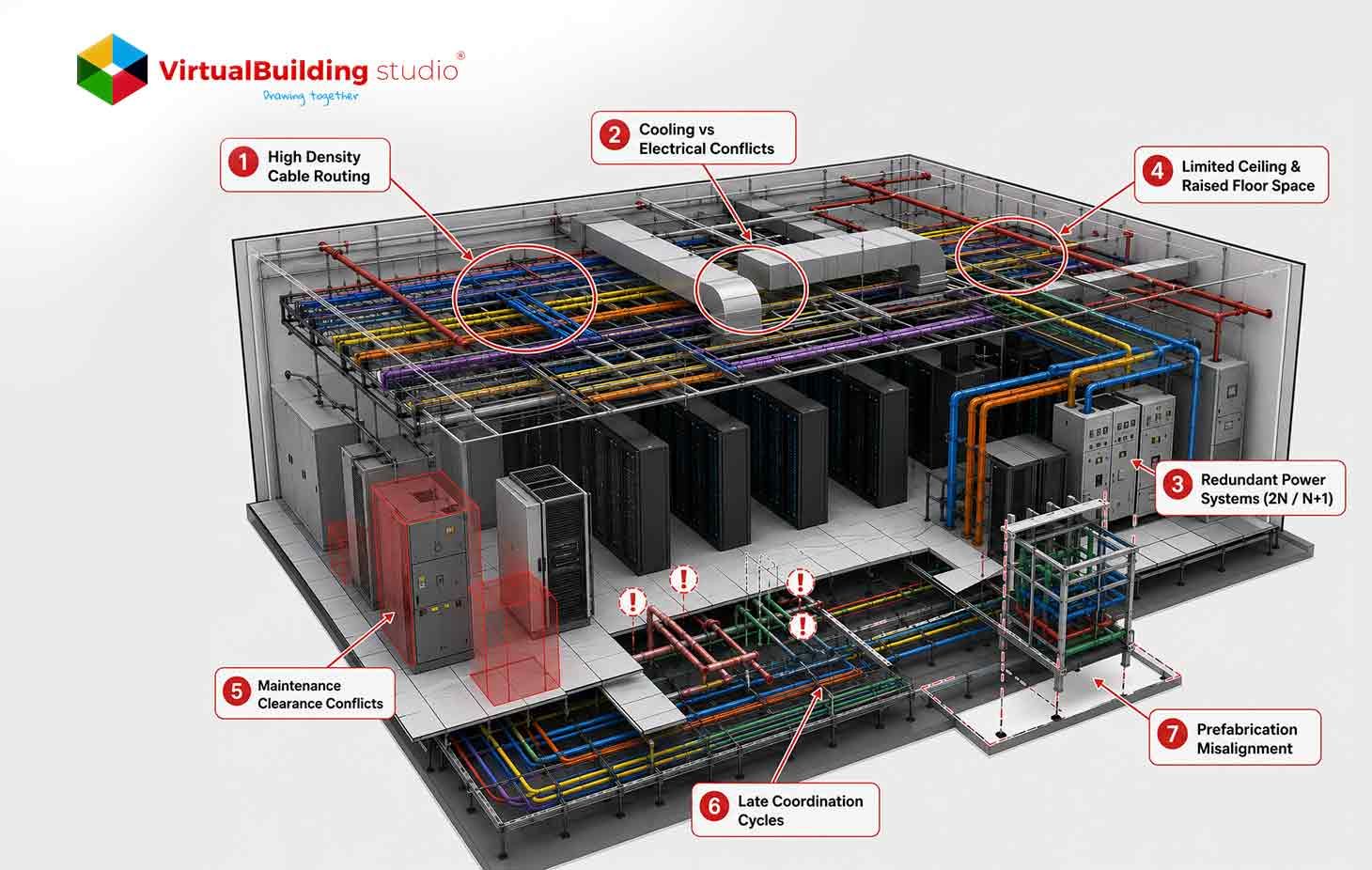
Challenge 1: High Density Cable Routing
Data centers route thousands of cables across multiple levels. Raised floor spaces carry heavy power feeds. Overhead ceilings hold fiber optic trays. Vertical risers connect systems across floors. Multilevel cable trays create extreme congestion in shared routing corridors. Cable tray overlaps emerge quickly in facilities with uncoordinated planning. Poor cable pathways obstruct cooling airflow in hot aisle configurations. Uncoordinated routing increases installation time along with long-term maintenance difficulty.
MEP Data Center Services address cable chaos through structured routing frameworks. A tiered tray hierarchy assigns each cable category to a defined elevation zone. Power trays occupy the highest elevation. Data trays sit at mid-level positions. Control wiring travels at the lowest tray level. Parametric modeling adjusts tray widths according to calculated cable loads. Teams use clash detection to catch conflicts between structural elements and adjacent services early. This approach supports accurate installation sequencing from the first day of construction.
Structured Solutions
- Define separate elevation zones for power trays, data trays, and control wiring across the entire facility
- Create spatial routing corridors through detailed 3D modeling for every cable category
- Use parametric models to adjust tray widths according to cable quantity calculations
- Run automated clash detection against structural elements and nearby services at every coordination cycle
- Document routing sequences in installation packages to guide field teams step by step
Challenge 2: Cooling vs Electrical Conflicts
Cooling infrastructure occupies prime ceiling space in every data center. Chilled water piping, along with CRAH units, competes directly with electrical busways for the same overhead zone. Cable trays from power distribution systems often block return air paths. Improper placement of electrical systems disrupts pressure balance across the floor. Thermal hotspots develop when cool air distribution meets obstruction in key zones. Electrical systems also generate heat that adds to the total cooling load.
A 2025 study in the Journal of Construction in Developing Countries analyzed 65 MEP clashes on a single project. Researchers found those unresolved conflicts generated additional costs of MYR 60,323.80 in a single case. In data centers, clash costs multiply because thermal consequences compound electrical rework. → Shah & Awang (2025), Journal of Construction in Developing Countries, 30(1): 199–219
Early coordination of HVAC and electrical systems prevents this financial exposure. Teams that plan both systems simultaneously produce clash-free layouts faster. Computational fluid dynamics simulations give designers a clear view of cold air distribution paths before construction begins. Coordinated design reviews align thermal management requirements with electrical routing plans at every stage.
Structured Solutions
- Start HVAC and electrical design development at the same project stage, progressing together in parallel
- Run CFD simulations to visualize cold air distribution paths and detect airflow obstructions
- Position cable trays away from cold aisles and return air plenums in all routing plans
- Conduct coordinated design reviews to align thermal management with routing requirements
- Verify airflow performance through simulation before issuing construction documents to the field
Challenge 3: Redundant Power Systems (2N / N+1)
Data centers require redundant power architectures to support continuous operations. In 2N configurations, teams duplicate entire power systems. N+1 configuration add backup components to each primary system. This duplication doubles cable routing requirements. Busways, along with switchgear connections, also multiply across the floor. Parallel routing creates spatial congestion that affects all adjacent MEP systems. Physical separation between redundant systems demands dedicated space allocations that teams often underestimate.
MEP coordination challenges in data centers reach peak complexity in redundant power environments. Lack of physical separation between primary systems compromises fault tolerance. Maintenance teams face serious access issues when routing lacks a clear system identity. Data center MEP coordination workflows address these issues through dedicated corridor planning. Clear visual zoning in the BIM model confirms compliance with Tier III along with Tier IV separation requirements.
Structured Solutions
- Create dedicated BIM routing corridors for each primary power path across the facility
- Assign separate corridors for backup systems with documented physical separation requirements
- Confirm compliance with Tier III or Tier IV separation requirements visually inside the model
- Label all power system paths clearly to support the maintenance team's identification in the field
- Validate redundancy boundaries through structured clash detection reviews at every milestone
Challenge 4: Limited Ceiling and Raised Floor Space
Ceiling voids hold HVAC ducts alongside chilled water pipes in the same vertical space. Raised floors carry cable trays along with fire protection systems below. All these systems compete for the same vertical inches. Overcrowding leads to restricted airflow. Increased pressure drops reduce cooling performance across the floor. Limited space forces installation teams to rework layouts on-site. Maintenance access becomes difficult when systems occupy the same elevation zone.
A zone allocation matrix gives each discipline a defined area of spatial ownership. Priority allocation positions HVAC along with main power routes first. Secondary systems fill the remaining space according to a documented discipline hierarchy. MEP Coordination in Data Center Projects improves dramatically when teams adopt this spatial governance approach. BIM visualization confirms full space utilization before any installation begins. Teams catch overcrowding issues in the model rather than in the field.
Structured Solutions
- Develop a zone allocation matrix before any discipline begins routing work on the project
- Assign spatial ownership for each system along the vertical and horizontal axes of the facility
- Model all systems in full detail to verify space utilization in three dimensions
- Reserve maintenance corridors as protected zones that clash detection flags as untouchable
- Review the matrix with all trade leads at the project coordination kickoff meeting
Challenge 5: Maintenance Clearance Conflicts
Switchgear with UPS systems requires defined clearance zones for safe operation. Chillers and pump assemblies carry similar spatial requirements. These zones allow periodic maintenance activities without obstruction. Traditional coordination focuses on physical geometry. It often misses functional clearance requirements from equipment manufacturers. Blocked access creates unsafe working conditions during maintenance cycles. Failure to meet clearance standards triggers regulatory inspections along with potential operational shutdowns.
MEP clash detection in data centers must address both physical overlaps and functional space requirements. A clearance envelope captures the access zone around each piece of equipment. Teams add these envelopes to the BIM model using manufacturer specifications. Safety code requirements inform the final envelope dimensions. Clash detection then flags any system that enters a protected clearance zone. This approach protects workers from the design stage onward.
Structured Solutions
- Add clearance envelopes to all major equipment objects in the BIM model at every design stage
- Source envelope dimensions directly from manufacturer specifications and applicable safety codes
- Run clash detection against clearance zones as a separate discipline rule set in every session
- Document all clearance requirements in the coordination log for regulatory review and approval
- Confirm that access routes remain open for inspection and repair activities throughout the design
Challenge 6: Late Coordination Cycles
Late clash detection wastes project time at the worst possible stage. Teams discover conflicts during fabrication or active construction phases. Rework at this stage costs far more than resolving conflicts during design. Outdated models create misalignment between disciplines. Small design inconsistencies escalate into major schedule delays. Budget overruns follow when teams address avoidable conflicts in the field.
Research in the construction industry indicates coordinated MEP modeling reduces field RFIs by 30 to 50 percent on complex projects. This reduction carries even greater weight in mission-critical data center work. → World Property Journal, 2025 — VDC Cost Reduction in Commercial Real Estate
The MEP Coordination Workflow for data centers requires weekly clash detection cycles from the design development stage. This frequency keeps models current across all disciplines. Teams resolve issues fast when coordination meetings happen on a fixed weekly schedule. A live coordination log tracks all open clashes along with assigned resolution owners. Structured cycles turn reactive firefighting into a proactive quality process.
Structured Solutions
- Start clash detection sessions at the Design Development stage of the project lifecycle
- Schedule weekly coordination cycles to maintain model accuracy across all discipline teams
- Use real-time collaboration tools to accelerate conflict resolution between trade coordinators
- Track clash resolution status in a live coordination log accessible to all project stakeholders
- Issue updated models to all disciplines after every coordination session closes for the week
Challenge 7: Prefabrication Misalignment
Prefabrication depends on accurate BIM models to produce off-site components. Incomplete models result in incorrect fabrication along with field rework. Misaligned components require on-site correction that adds time and cost. Teams lose the key benefit of prefabrication when fabrication packages go out too early. Coordination gaps between design and fabrication teams create wasteful production cycles.
Data center BIM challenges in prefabrication center on model detail levels. LOD 350 models include connection details that support assembly planning. LOD 400 models carry full fabrication information for off-site production. MEP BIM for Data Centers at LOD 400 allows fabricators to generate spool drawings directly from the coordinated model. A US hyperscale provider reduced overall project delivery by 25 percent through BIM-supported prefabricated MEP skid design. Teams that reach LOD 400 before releasing packages eliminate the most costly fabrication errors.
Structured Solutions
- Bring BIM models to LOD 350 before completing final coordination reviews with all disciplines
- Advance models to LOD 400 before releasing any fabrication drawings to vendors or shops
- Coordinate directly with fabrication teams during the model development phase of the project
- Generate spool drawings and shop drawings from the coordinated BIM model for accuracy
- Confirm all connection details in the model match the field installation requirements exactly
Summary: Challenge → Impact → BIM Solution
| Challenge | Impact | BIM Solution |
|---|---|---|
| High-Density Cable Routing | Congestion, airflow blockage, and maintenance difficulty | Tiered tray hierarchy with BIM routing zones |
| Cooling vs Electrical Conflicts | Thermal inefficiency, overheating risk | Early HVAC and electrical coordination with CFD |
| Redundant Power Systems (2N / N+1) | Doubled congestion, fault tolerance risk | Dedicated routing corridors per power path |
| Limited Ceiling and Raised Floor Space | Overcrowding, restricted airflow | Zone allocation matrix with 3D utilization modeling |
| Maintenance Clearance Conflicts | Unsafe access, regulatory exposure | Clearance envelope clash detection rules |
| Late Coordination Cycles | Rework, schedule delays, cost overruns | Weekly clash detection from the Design Development stage |
| Prefabrication Misalignment | Fabrication errors, on-site rework | LOD 350 to 400 modeling before fabrication release |
Conclusion
Data center MEP coordination demands early action along with detailed spatial management. Strong interdisciplinary communication supports the entire coordination effort. Most coordination problems originate from insufficient clash detection frequency at early design stages. Teams that adopt BIM coordination workflows from the design development stage resolve the majority of conflicts before fabrication begins.
Structured zone allocation, along with tiered routing hierarchies, addresses the root causes of field failures. Clearance envelope modeling adds another layer of safety throughout the project lifecycle. The seven challenges in this article each carry a structured solution that teams can apply immediately. Better coordination improves project timelines along with operational safety across the full facility lifecycle.


.jpg)