 +1 (409) 800-6601
 contact@virtualbuildingstudio.com

Manual Slope Verification
Every underfloor sanitary run was checked and adjusted by hand at each connection, so gravity slopes held their pitch instead of breaking inside Revit's piping engine.

A 98,000 sq. ft. Bank HQ needed LOD 350 plumbing coordination across three connected building zones, delivered over eight months by a six-person modeling team.
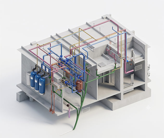
A 98,000 square foot bank headquarters was rising on a 10-acre campus in Iowa, with completion planned for 2026. The five-story building combines corporate offices with a retail banking branch, so the plumbing system had to serve two different occupancy types under one roof. Underfloor sanitary lines run beneath the courtyard and parking levels before tying into the main stacks, and the mechanical piping covers a chilled water loop, a multi-stage boiler network, and a dedicated domestic hot water circuit. Over eight months, a six-person team modeled the plumbing system to LOD 350 and coordinated it against architecture and structure, so the construction crew had a plan built from real field conditions instead of assumptions.
 Project Type Commercial
 Level of Development LOD 350
 Manpower Used 6 Resources
 Location USA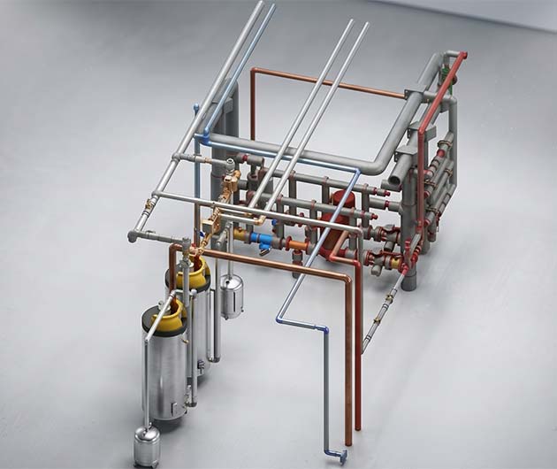
Navisworks supported the coordination process, while the team developed the plumbing model and related documentation in Revit.
 Autodesk Revit
 Navisworks
The project started with design files and requirements that guided the development of coordinated plumbing and mechanical deliverables.
A headquarters of this size brings several plumbing coordination demands together. The project also had to accommodate systems that required careful routing through limited building space.
The centralised mechanical room contains chilled water systems and boiler networks that need careful planning of the physical layout.
Tight envelopes in penthouses require precise routeing in space to prevent physical conflicts between trades.
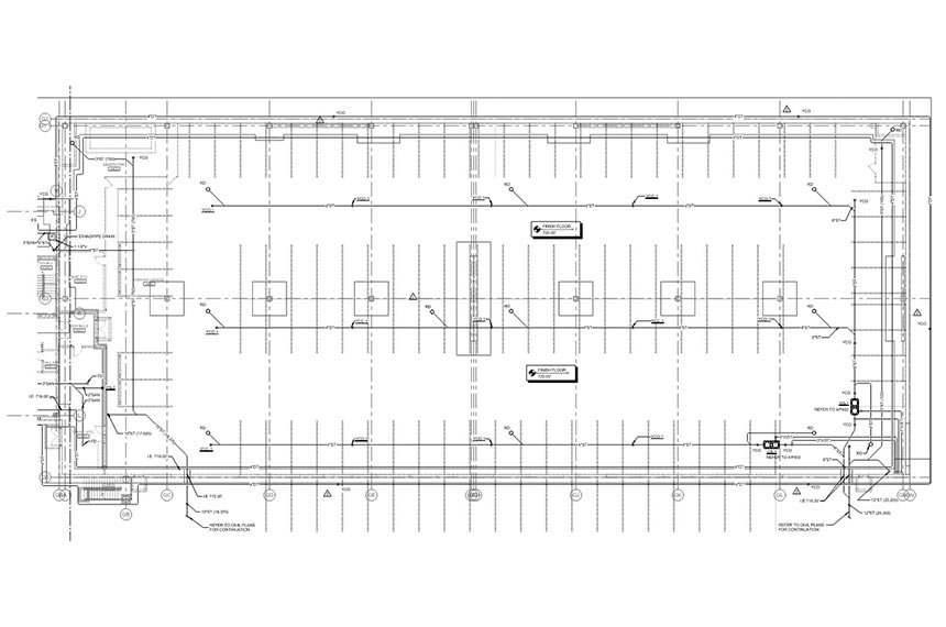
Accurate slopes are needed to provide good fluid dynamics for underfloor sanitary networks prior to pouring slabs.
Plumbing lines shall be positively separated from adjacent structural elements and mechanical piping.
Each pain point needed a specific fix on the modeling side, built around accuracy, sequencing and constant verification against the design intent.
Every underfloor sanitary run was checked and adjusted by hand at each connection, so gravity slopes held their pitch instead of breaking inside Revit's piping engine.
Chilled water and boiler piping were routed in a set order against the structural grid, giving each system a defined path through the restricted envelope.
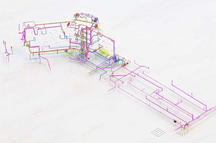
The waste and vent network was built as one connected system from the courtyard through the underfloor zone to the parking level, closing off transition-point clashes.
Riser diagrams were built to LOD 350 using real fitting and fixture data, so the main restroom stack was ready for fabrication, not just design review.
A standing review cycle caught design changes early and folded them into the model without undoing coordination work already signed off.
Our Project Execution Strategy
The team modeled the plumbing system zone by zone, checking each stage against architecture and structure so clashes surfaced early. Every flagged clash went through resolution and quality review before the model moved forward.
Project Information Review
PDF drawings, equipment schedules and LOD requirements were reviewed before modeling began.
Project Information Review
PDF drawings, equipment schedules and LOD requirements were reviewed before modeling began.
BIM Standards and Model Setup
Model templates and nomenclature were developed to project standards.
BIM Standards and Model Setup
Model templates and nomenclature were developed to project standards.
Plumbing and Mechanical Piping Modeling
Modeler created sanitary lines and mechanical piping at LOD 350 zone by zone.
Plumbing and Mechanical Piping Modeling
Modeler created sanitary lines and mechanical piping at LOD 350 zone by zone.
Architectural & Structural Coordination
The plumbing model was checked against architecture and structure at each stage.
Architectural & Structural Coordination
The plumbing model was checked against architecture and structure at each stage.
Clash Detection
Navisworks runs flagged conflicts between plumbing, structure and other systems.
Clash Detection
Navisworks runs flagged conflicts between plumbing, structure and other systems.
Clash Resolution
Flagged clashes were corrected and re-checked before moving to the next zone.
Clash Resolution
Flagged clashes were corrected and re-checked before moving to the next zone.
Quality Control
All connections have been cross checked to the input drawings for accuracy.
Quality Control
All connections have been cross checked to the input drawings for accuracy.
Final Model Validation and Handover
The project lead validated final model and handed over to the construction team.
Final Model Validation and Handover
The project lead validated final model and handed over to the construction team.
Using the coordinated plumbing model, the construction team detect issues before they got to the field and this help them keep the project on schedule.
The team identified plumbing conflicts in the model to avoid during construction, saving money.
BIM scope of plumbing was delivered on time within the eight-month window.
The project stayed on track thanks to coordinated modelling and rapid problem solving.
The team was accurate on every plumbing model and document that was delivered.
Let's discuss your requirements and see how our expertise can help on your next project.