

CAD to BIM Conversion
Converted 2D CAD MEP documentation into structured Revit models.

CAD to BIM conversion producing a LOD 400 coordinated model with shop drawings, hanger drawings, and sleeve drawings for a commercial project in New York.
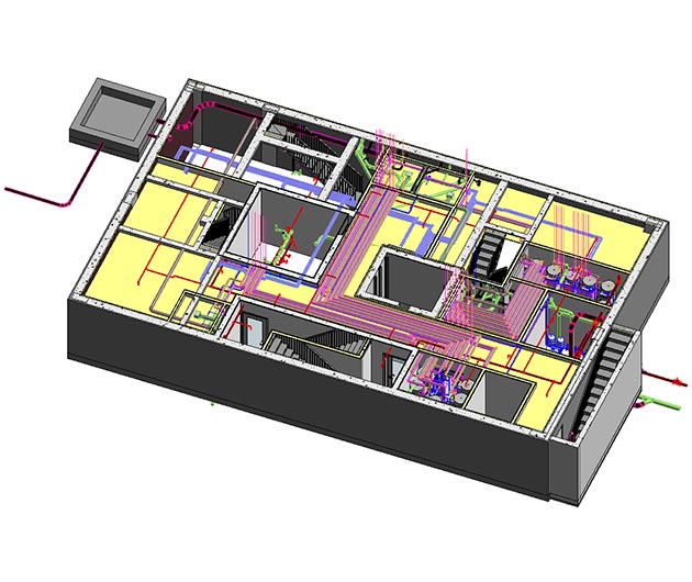
This commercial project in New York required converting CAD documentation into a LOD 400 coordinated BIM model with MEP-focused deliverables. Our team developed the coordinated model and produced shop, hanger, and sleeve drawings for construction.
The deliverables supported MEP installation planning with accurate, coordinated drawing sets derived from the BIM model.
 Level of Development LOD 400
 Discipline MEP
 Location New York, USA
 Project Type Commercial Building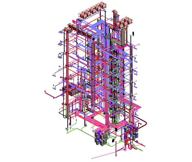
CAD to BIM conversion and MEP coordination ran in Autodesk Revit with Navisworks for clash detection.
 Revit
Revit Navisworks
From 2D CAD MEP drawings to a LOD 400 coordinated model with shop, hanger, and sleeve drawing sets.
Commercial MEP projects in New York require coordinated BIM models and fabrication-ready drawing sets.
Legacy CAD MEP drawings must be converted accurately to support LOD 400 coordinated modeling.
Hanger and sleeve placements require precise coordination with structural elements.
Fabrication-ready shop drawings must reflect the coordinated BIM model accurately.
MEP systems must align with architectural and structural constraints in dense commercial buildings.
CAD to BIM conversion followed by LOD 400 coordination and MEP drawing production.
Converted 2D CAD MEP documentation into structured Revit models.
Developed coordinated MEP models at LOD 400 aligned with reference disciplines.
Produced shop drawings from the coordinated model for fabrication and installation.
Generated hanger and sleeve drawing sets with precise placement coordinates.
A Structured CAD to BIM Workflow - Phase by Phase
Delivery moved from CAD intake through BIM conversion, coordination, and MEP drawing production.
CAD Intake and Standards Review
CAD Intake and Standards Review
CAD Intake and Standards Review
CAD Intake and Standards Review
CAD to BIM Conversion
CAD to BIM Conversion
CAD to BIM Conversion
CAD to BIM Conversion
LOD 400 Coordinated Modeling
LOD 400 Coordinated Modeling
LOD 400 Coordinated Modeling
LOD 400 Coordinated Modeling
MEP Coordination and Clash Detection
MEP Coordination and Clash Detection
MEP Coordination and Clash Detection
MEP Coordination and Clash Detection
Shop, Hanger, and Sleeve Drawing Production
Shop, Hanger, and Sleeve Drawing Production
Shop, Hanger, and Sleeve Drawing Production
Shop, Hanger, and Sleeve Drawing Production
Final Review and Delivery
Final Review and Delivery
Final Review and Delivery
Final Review and Delivery
LOD 400 coordinated model with shop, hanger, and sleeve drawings delivered for the New York commercial project.
MEP-coordinated BIM model developed at LOD 400 from CAD inputs.
Fabrication-ready shop drawing sets extracted from the coordinated model.
Precise hanger placement drawings for MEP installation.
Coordinated sleeve drawings aligned with structural penetrations.
Let's discuss your requirements and see how our expertise can help on your next project.