
MEP BIM modeling forms the technical foundation for integrating Mechanical, Electrical, Fire Protection, and Plumbing systems within modern construction environments. It translates engineering calculations, routing logic, equipment data, and spatial constraints into coordinated 3D models used for design validation, fabrication planning, and installation sequencing. Even when BIM professionals operate with advanced platforms such as Navisworks, Revit, AutoCAD MEP, and Construction Cloud.
These modeling inconsistencies continue to appear in live construction workflows. Digital platforms process geometry and metadata with high precision, yet output quality depends entirely on engineering inputs, parameter control, and coordination structure. BIM platforms surface design calculation gaps, clearance conflicts, and data inconsistencies at early stages within the model environment.
Common technical outcomes of MEP BIM modeling mistakes are measurable and directly linked to constructability. Duct mains, hydronic piping, and cable containment systems frequently intersect structural beams or slab drops when routing logic lacks spatial validation. Incorrect slab or roof penetration placement affects waterproofing, fire stopping, and inspection approvals. HVAC airflow calculations or electrical load sizing errors propagate into oversized or undersized systems. Nonstandard fittings created during modeling disrupt fabrication sequences. Excessive geometric detail increases file size and degrades model performance, while incomplete specification data generates documentation inconsistencies. Field adjustments, schedule compression, and cost escalation follow when such modeling gaps transition into site execution.
Tighter construction timelines and skilled labor shortages amplify the operational impact of even small digital deviations. Tight ceiling spaces and plant rooms often require multiple trades to install their systems at the same time within limited service areas, increasing coordination challenges.
A misaligned duct sleeve, incorrect static pressure assumption, or misplaced cable tray offset can interrupt prefabrication and delay installation crews. Large infrastructure delivery programs illustrate the scale of coordination complexity. Industry data from 900+ BIM engagements indicates that absence of structured execution planning repeatedly correlates with coordination breakdown and performance inefficiencies.

Why MEP BIM Errors Happen and How to Prevent Them
MEP BIM coordination challenges originate from process gaps rather than software capability. Inconsistent LOD definitions, unstable engineering inputs, uncontrolled family libraries, weak clash review cycles, and unclear file governance create modeling variability inside federated environments. As multiple disciplines contribute to shared models under compressed schedules, structured review checkpoints and defined responsibilities directly influence coordination clarity and construction readiness.
Inaccurate Level of Development in MEP Models
Level of Development misalignment appears when detailed modeling begins before engineering calculations stabilize. Systems may be routed without finalized thermal loads, airflow rates, water flow calculations, pressure loss validation, or confirmed equipment capacities. LOD 350–400 content sometimes enters the model during early design phases without fabrication intent. Prefabrication requirements may also be excluded from early routing strategies, creating disconnects between digital geometry and construction sequencing.
Common indicators include:
- LOD 300 models interpreted as LOD 400 fabrication deliverables
- Missing hanger supports and connection detailing
- Duct and pipe slopes not validated against hydraulic calculations
- Ambiguity between design-intent and construction responsibility
Fabrication-level geometry introduced before routing stability
Such conditions influence downstream accuracy. Quantity takeoffs fluctuate, system dimensions change late, and coordination cycles extend. HVAC systems may appear oversized or undersized due to premature detailing. Industry case data from California (2024 commercial study) recorded a 20% reduction in rework only after structured coordination and correct Level of Development Details (LOD) alignment were implemented, demonstrating measurable performance impact.
How to avoid it
Finalize engineering calculations before detailed modeling begins. Align LOD 100–500 progression with project phase maturity. Stabilize primary routing corridors before introducing fabrication detail. Validate slopes, velocities, and pressure losses prior to clash sign-off. When prefabrication is targeted, prepare spool ready deliverables aligned with approved submittals.
Incorrect Family Selection and Parameter Management
Family libraries directly influence model integrity, scheduling accuracy, and facility data output. Modeling teams often import manufacturer families containing excessive geometric detail such as bolts, internal components, or decorative elements not required for coordination. Parameter structures may vary between disciplines, limiting data extraction reliability. Plumbing fixtures or equipment may lack non-physical properties such as voltage, load classification, or maintenance data. Insulation thickness may not be embedded within sleeve sizing logic.
Common indicators include:
- Generic families replacing approved manufacturer content
- Missing system classification parameters
- Inconsistent shared parameter mapping
- Incorrect connector definitions
- Duplicate libraries across teams
File performance increases in size when heavy geometry accumulates, sometimes exceeding the architectural model footprint. Schedules and quantity takeoffs may display inconsistent values due to parameter mismatch. Facility management exports may present incomplete metadata.
How to avoid it
Develop lightweight, purpose-built families aligned with coordination requirements. Define required physical and non-physical parameters before modeling begins. Standardize shared parameter files across trades. Integrate clearance zones within equipment families. Align sleeve sizing logic with approved submittals and curb references.
Executive Summary: MEP BIM Risk & Control Overview
| Risk Area | What’s Really Going Wrong | Business Impact | Leadership Control Action |
|---|---|---|---|
| LOD Misalignment | Modeling progresses before engineering inputs stabilize | Rework, budget variance, delayed coordination sign-offs | Enforce phase-based LOD gates tied to engineering approval milestones |
| Uncontrolled Family Libraries | Inconsistent parameters and heavy geometry across teams | File instability, inaccurate quantity takeoffs, unreliable FM data | Standardize shared parameters and approve centralized family libraries |
| Model Detail Imbalance | Over modeling or missing constructability elements | Reduced performance, prefabrication inefficiency, site clashes | Define modeling scope aligned with construction intent, not visual detail |
| Unstructured Clash Detection | Clash testing performed on unstable or mismatched models | Extended coordination cycles and RFI backlog | Schedule clash reviews after routing maturity; assign issue ownership accountability |
| Weak File Governance | Inconsistent naming, version confusion, merged files | Documentation errors and metadata inconsistency | Mandate structured CDE workflows with revision tracking controls |
| BEP Non-Compliance | Undefined responsibilities and inconsistent LOD interpretation | Coordination ambiguity and duplicated effort | Implement enforceable BIM Execution Plan checkpoints from project kickoff |
Overmodeling and Under-Modeling of MEP Components
Model detail balance directly affects coordination efficiency and file performance. Overmodeling occurs when internal mechanical components, excessive fittings, or nonstandard cut pieces are introduced without construction necessity. Under-modeling appears when clearance zones, insulation thickness, hanger systems, or maintenance access areas are omitted. Both conditions influence constructability evaluation and prefabrication readiness.
Common indicators include:
- Detailed internal equipment geometry not required for installation
- Branded components imported without simplification
- Manual repetitive geometry instead of parametric content
- Omitted supports or access zones
- Routing without fabrication-length logic
File opening speed, export time, and documentation productivity are directly influenced by model weight. Fabrication efficiency declines when nonstandard components dominate spool layouts. Coordination clarity reduces when access and clearance requirements remain undefined.
How to avoid it
Model elements required for coordination and construction scope only. Use parametric, fabrication-aligned content. Design around standard fabrication lengths. Represent insulation, supports, and access zones clearly without excessive geometric detail. Maintain balance between 3D content utilization and model performance.
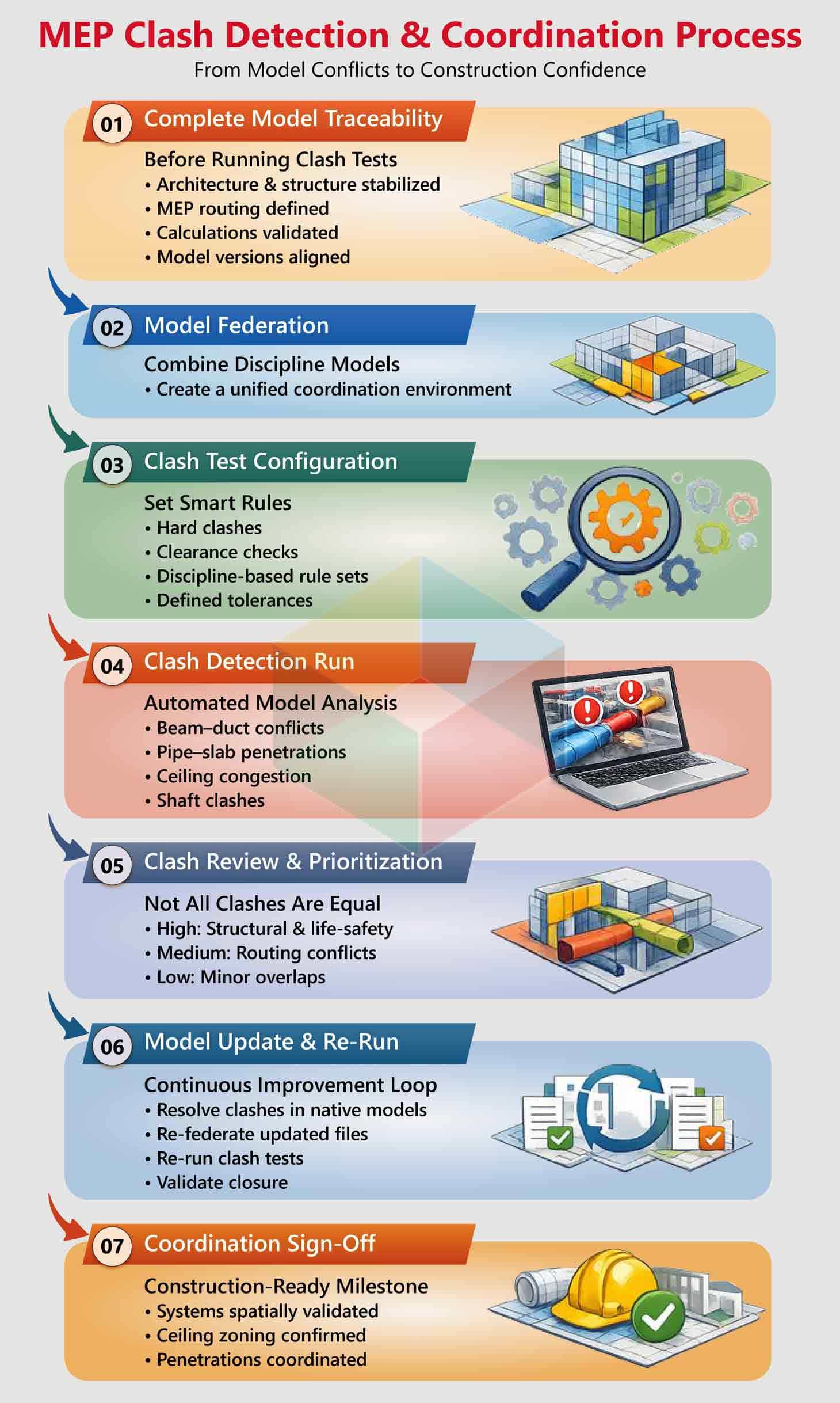
Poor Clash Detection and Coordination Practices
Clash detection produces value when executed against stable, mature models. Running clash tests during architectural revision cycles or before system routing stabilizes generates excessive reports. Teams may conduct coordination using manual 2D overlays instead of structured model-based detection. Isolated discipline workflows using different model versions increases inconsistency. Late involvement of MEP consultants also influences routing feasibility.
Common indicators include:
- Hundreds of low-priority clash reports
- Beam–duct or pipe–slab conflicts at advanced stages
- Ceiling congestion between HVAC, plumbing, and electrical
- Slow RFI turnaround cycles
Untracked resolution ownership
Large-scale infrastructure delivery demonstrates coordination scale. During the Crossrail program , more than 250,000 clashes were detected and resolved digitally prior to construction, illustrating the volume of conflicts that structured workflows can process within virtual environments.
How to avoid it
Initiate coordination after design maturity stabilizes. Use automated clash detection tools within structured rule sets. Re-run clash tests following major revisions. Track issue ownership and resolution cycles. Establish ceiling zoning hierarchy early and adopt 3D routing as the primary workflow.
Improper Naming Conventions and File Management
File governance affects collaboration speed, version control, and metadata clarity. In federated BIM environments, inconsistent naming standards and uncontrolled file merging increase model weight and confusion. External DWG, PDF, or image files may enter the environment without audit. Direct file merging instead of linking introduces duplication and metadata inconsistency.
Common indicators include:
- Randomized file naming structures
- Merged files replacing linked references
- Disorganized folder hierarchies
- Missing revision tracking logs
- Uncontrolled external content imports
Model size expands unnecessarily when unmanaged content accumulates. Version ambiguity influences coordination meetings and documentation issuance. Metadata inconsistency affects schedules and downstream deliverables, increasing exposure to MEP shop drawing errors.
How to avoid it
Establish structured naming protocols within the BIM Execution Plan. Link external files instead of importing them directly. Audit file size and metadata prior to integration. Implement centralized Common Data Environment version control procedures with defined revision logs.
Lack of Standardized BIM Execution Plan Compliance
A BIM Execution Plan defines modeling standards, LOD targets, task allocation, information exchange protocols, and review frequency. When BEP requirements are interpreted differently across trades, coordination variability increases. Some teams view BEP documentation as applicable only to large-scale programs, while smaller projects benefit equally from structured governance.
Common indicators include
- Undefined modeling responsibilities
- Inconsistent LOD interpretation
- Misaligned collaboration platforms
- Irregular model sharing intervals
- Software mismatch between teams
Tool incompatibility, responsibility overlap, and coordination ambiguity can appear when BEP structure lacks clarity. Role definition and technology alignment directly influence model consistency.
How to avoid it
Develop a practical and implementable BEP at project initiation. Define roles, LOD standards, naming conventions, review cycle frequency, and collaboration platforms clearly. Maintain LOD alignment across trades and document review checkpoints throughout coordination phases.
Practical Strategies to Fix MEP BIM Mistakes
Controlling BIM modeling errors in construction requires production-level governance rather than reactive correction. Effective teams adopt a BIM-first coordination framework supported by engineering validation, structured review cycles, and measurable quality checkpoints. Daily automated scans, weekly interdisciplinary reviews, and milestone audits create controlled model progression. When geometry, parameters, and calculations are validated continuously, coordination becomes predictive instead of corrective.
Structured Quality Control Strategies
- Engineering-first modeling: finalize load, flow, and pressure calculations before routing
- Daily automated model validation (element placement, duplication, parameter checks)
- Weekly interdisciplinary coordination meetings
- Phase-based milestone audits prior to model release
- Automated clash detection using Navisworks Manage and cloud review platforms
- Parameter and IFC validation through model checking tools such as Solibri
- Defined clash tolerance thresholds and coordination hierarchy (e.g., gravity drainage priority over electrical containment)
- Embedded clearance zones within equipment families
- Standardized naming conventions and unified shared parameter files
- Version control within a centralized Common Data Environment (CDE)
- Early alignment of prefabrication scope with LOD 350–400 models
- Three-level internal audits (duplication, constructability, standards compliance)
- Cross-validation of geometry with engineering calculations: slopes, velocities, pressure losses, access zones
- Integrated RFI tracking log connected to model updates
- 4D BIM scheduling aligned with construction milestones
- Structured change-management workflow with automated clash reruns
Hardware configuration also influences BIM productivity. Revit-based workflows operate primarily on single-thread processing for modeling tasks, utilizing additional cores during rendering and exports. Workstations with up to six high-speed CPU cores provide efficient performance. CAD-optimized graphics cards provide stable viewport performance. When these controls are embedded into MEP BIM Modeling Services and MEP coordination Services workflows, fabrication readiness and schedule predictability.
Conclusion
MEP BIM performance improves when engineering calculations, routing logic, data schemas, and coordination sequencing operate within a controlled execution framework aligned to measurable production targets. Within environments such as Autodesk Revit, validated airflow and pressure-loss calculations, slope-controlled gravity systems, load-balanced electrical networks, and manufacturer-aligned equipment families form the foundation of fabrication-ready modeling.
Parameter governance through shared GUID standards, model health audits, rule-based clash matrices, and LOD 350–400 spool alignment create coordinated outputs directly consumable for procurement and installation. When coordination cycles synchronize with structural release milestones and 4D sequencing logic, federated MEP models transition into installation-grade digital assemblies that support prefabrication accuracy, logistics planning, access compliance, and schedule reliability in high-density service environments.
Planning to implement BIM in your next development?