Modern MEP projects operate in distributed execution environments. Mechanical engineers design ductwork layouts in one country, electrical engineers model cable trays and containment in another and plumbing teams coordinate risers from a third location. This global delivery model increases coordination risk when teams exchange disconnected files, apply manual updates, and communicate revisions through emails. File-based workflows create version conflicts, overwrite errors, and delayed clash detection. When one discipline modifies a shaft opening or ceiling void without synchronized updates, downstream services misalign and compound coordination errors.
Cloud-based MEP BIM changes this execution model by centralizing model data within a controlled digital platform. Teams access a live federated model instead of downloading isolated discipline files. The platform synchronizes updates in real time, logs revision histories automatically and records user activity for traceability.
BIM managers assign role-based permissions, track model changes and validate design updates against coordination standards. This feature-centric structure supports accurate clash detection, structured approval workflows, and model-based decision making. MEP BIM Services delivered through cloud platforms maintain data continuity across design development, coordination, and construction documentation stages.
This blog explains how these workflows improve remote collaboration, reduce interdisciplinary design conflicts, protect model integrity, and support advanced coordination processes. It examines centralized data environments, automated revision tracking, structured issue management, and real time model access. BIM professionals who manage distributed MEP teams require systems that control information flow while maintaining geometric and data accuracy. Cloud-based MEP BIM provides that operational framework.
What is Cloud-based MEP BIM?
Cloud-based MEP BIM refers to mechanical, electrical, and plumbing modeling workflows deployed on a centralized CDE. where discipline models connect through structured data containers rather than isolated local files. In a traditional server-based setup teams copy RVT files, create detached models and manually re-link references.
In a cloud environment integrated with Autodesk Revit and hosted on platforms such as Autodesk Construction Cloud the central model resides online. Team members work on local cache files that synchronize directly with the cloud-hosted master file. The system manages element ownership, worksets, and publishing states, which reduces overwrite conflicts and untracked geometry changes. This architecture supports distributed authoring without fragmenting model integrity.
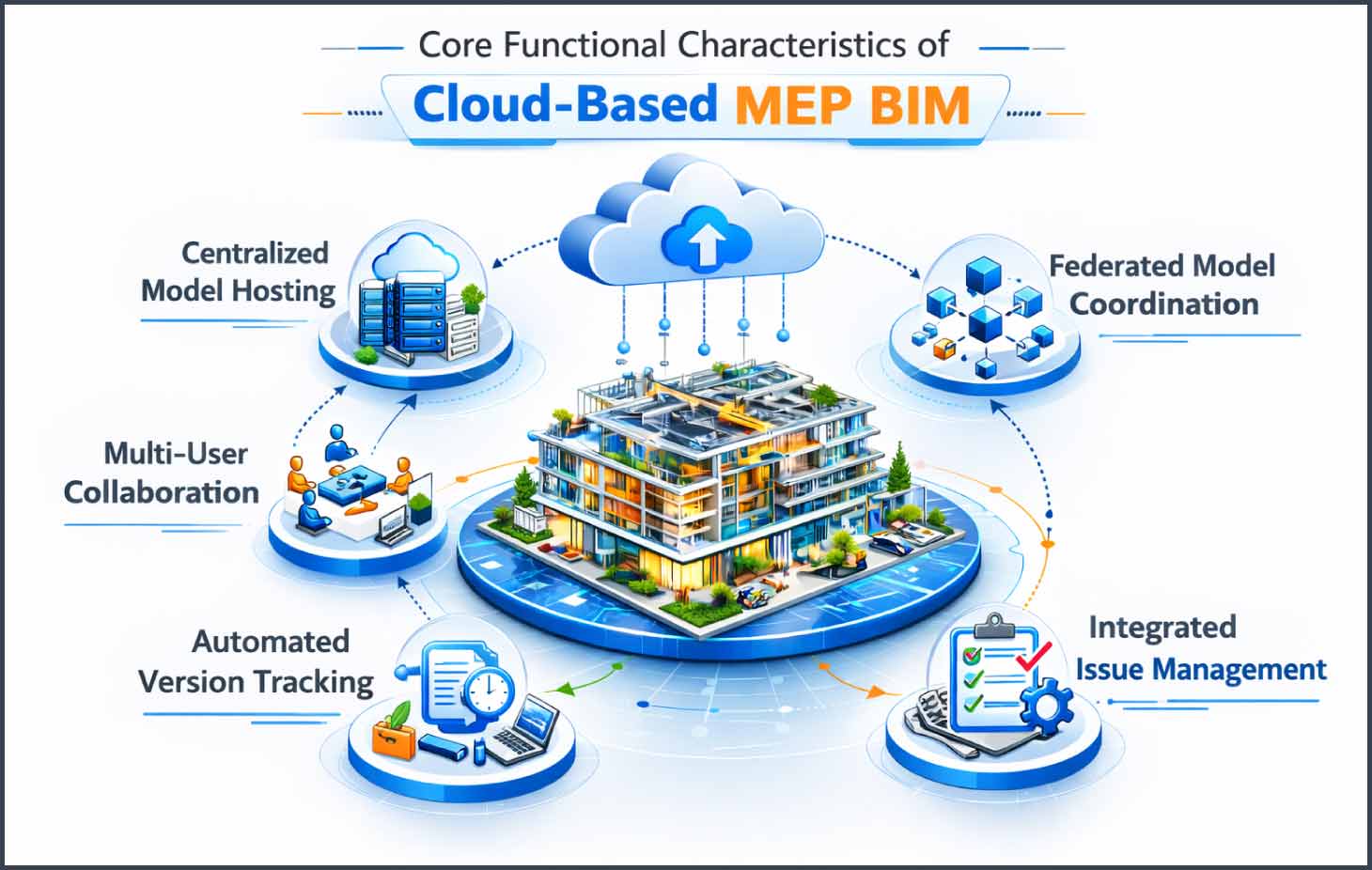
Core Functional Characteristics
- Cloud-Hosted Central Model Architecture: The primary RVT file exists in the CDE, not on an internal server. Local copies function as synchronized working files.
- Element-Level Worksharing Control: The system assigns ownership of model elements and worksets to prevent simultaneous edits on the same objects.
- Automated Model Versioning with Audit Trails: Each publish cycle generates a time-stamped version with change comparison capability.
- Federated Model Aggregation: Mechanical, electrical, plumbing, fire protection and structural models aggregate into a coordinated cloud workspace without file merging.
- Integrated Clash Detection Environment: Coordination models feed directly into cloud-based clash modules aligned with tools such as Autodesk Navisworks.
- Metadata Transparency: Parameters, system classifications, and asset properties remain accessible for review, filtering, and validation.
- Permission-Based Access Hierarchy: Administrators define contributor, reviewer, and approval roles within the project workspace.
It operates as a structured data environment rather than a file exchange mechanism. When a plumbing engineer modifies pipe invert levels, the synchronization updates connected MEP links and flags coordination impacts during clash review. The system records who changed the geometry when the change occurred, and which version preceded it. BIM professionals working in distributed environments gain measurable control over revision tracking, model federation, and cross-discipline visibility.
Key Challenges in Traditional MEP Collaboration Workflows
Traditional MEP collaboration operates through local servers, manual version control, and milestone-based model federation. This structure shapes how teams exchange data, detect clashes, and manage approvals. In dense MEP zones where ceiling voids, risers, and plant rooms contain high service density, coordination precision depends heavily on how information flows between disciplines.
Fragmented File Exchange
In traditional environments each discipline maintains its own central model on internal servers. Mechanical teams host HVAC models, electrical teams store containment and lighting layouts separately, and plumbing teams manage piping networks in isolated directories. Model exchange occurs through periodic uploads, email attachments, or shared network drives. Each transfer produces a static snapshot of the model at a specific time. This structure creates coordination checkpoints instead of continuous synchronization. Teams align models during review sessions rather than during daily authoring activities.
Key Workflow Characteristics Include
- Separate discipline-specific central files stored on independent servers
- Manual upload and download cycles during coordination milestones
- File naming conventions used for revision identification
- Linked models updated at scheduled intervals rather than continuously
- Coordination models built by manually aggregating discipline files
Limited Visibility into Design Changes
It tracks revisions at file level rather than element level. When engineers resize ducts, adjust cable tray elevations, or modify pipe slopes, the system records the updated file version but does not automatically generate structured change intelligence across disciplines. Design awareness depends on meeting discussions and manual comparison exercises.
Workflow Characteristics Include
- File-based revision history instead of object-level change logs
- Manual model comparison using exported reports
- Coordination meetings used to communicate geometric adjustments
- Screenshot-based markups referencing static model views
- RFI generation triggered after clash identification during reviews
In congested ceiling zones a 50 mm elevation shift in a main duct can affect containment offsets and sprinkler branch routing. Without continuous visibility, change awareness remains meeting-driven rather than system-driven.
Siloed Discipline Workflows
Mechanical, electrical, and plumbing teams complete modeling packages independently before federating models. Each discipline optimizes its routing logic based on internal constraints such as airflow requirements, cable fill ratios, or pipe gradient standards. Integration occurs after substantial modeling progress.
Operational Characteristics Include
- Discipline-specific modeling schedules aligned to internal deliverables
- Model federation performed during scheduled coordination workshops
- Clash detection executed at predefined milestones
- Design adjustments implemented after multi-discipline review cycles
- Fabrication detailing initiated following coordination approval
In high-density plant rooms and riser shafts, service routing follows strict clearance and access rules. When disciplines optimize layouts independently, coordination refinement occurs in concentrated review phases rather than through continuous interaction.
Delayed Approvals and Communication Gaps
Traditional approval workflows operate outside the live modeling environment. Designers export drawings and coordination views as PDFs for review. Consultants annotate documents, and teams consolidate feedback manually. Approval status tracking takes place in spreadsheets or email threads rather than within the model ecosystem.
Process Characteristics Include
- Drawing-based approval cycles detached from live 3D geometry
- Manual tracking of review comments across email chains
- Spreadsheet-based issue registers maintained separately from models
- Contractor validation based on issued drawing revisions
- Procurement triggered after milestone-based coordination clearance
This structure organizes communication around document exchanges instead of object-linked issue management. In fast-track MEP projects, approval sequencing follows document circulation timelines rather than synchronized model validation cycles.

How Cloud Platforms Enable Real-Time MEP BIM Collaboration
Cloud environments convert file-driven exchanges into structured, model-centric workflows for advanced coordination. Teams interact inside a connected Common Data Environment where geometry, system parameters, and coordination data update in controlled publishing cycles. This structure supports synchronized authoring, automated federation, and measurable coordination transparency.
Real-Time Model Federation
Cloud platforms aggregate discipline-specific authoring models into a continuously updating coordination space. Mechanical, electrical, plumbing, architectural, and structural teams publish models from tools such as Autodesk Revit to a shared CDE hosted on Autodesk Construction Cloud. The platform references published datasets and compiles them into a federated coordination model without manual merging or file reconstruction
The federation engine recalculates spatial relationships between elements after each publish cycle. When a mechanical engineer increases duct cross-section due to airflow recalculation, the updated geometry appears in the shared coordination environment. Electrical containment routing and plumbing offsets adjust during review based on the refreshed model state. This workflow supports live clearance validation, service zone analysis, and shaft alignment checks during active modeling stages.
Live Data Synchronization
Cloud platforms synchronize discipline models through structured publish workflows linked to the central cloud repository. Designers modify system layouts, adjust equipment parameters, and update elevations within their authoring environment. The platform transmits these changes during synchronization and logs metadata such as timestamp, author identity, and model version number.
Project dashboards provide measurable coordination indicators including publish frequency, open coordination items, and discipline specific progress tracking. Stakeholders access updated sheets, schedules and 3D views through browser-based viewers without requesting exported files. Many case studies report that cloud-based BIM improves productivity by up to 30% through centralized model access and updated data exchange. This measurable improvement reflects reduced coordination latency and structured information visibility.
Cloud-Based Clash Detection Workflow
The Cloud-based clash detection workflow operates directly inside the federated cloud environment. Coordination modules aligned with tools such as Navisworks and BIM 360 Model Coordination execute automated spatial interference checks against the latest published models. BIM coordinators define clash matrices based on discipline combinations, element categories, and tolerance thresholds measured in millimeters
The system performs rule-based clash scanning after every publish event. Its groups clash by location, system classification, or severity level. Engineers review clashes within the model viewer, isolate elements in 3D space, and assign issues to responsible disciplines. The platform records resolution status changes with user identification and time stamps. This workflow supports early geometric validation, structured accountability, and reduced fabrication-stage adjustments.
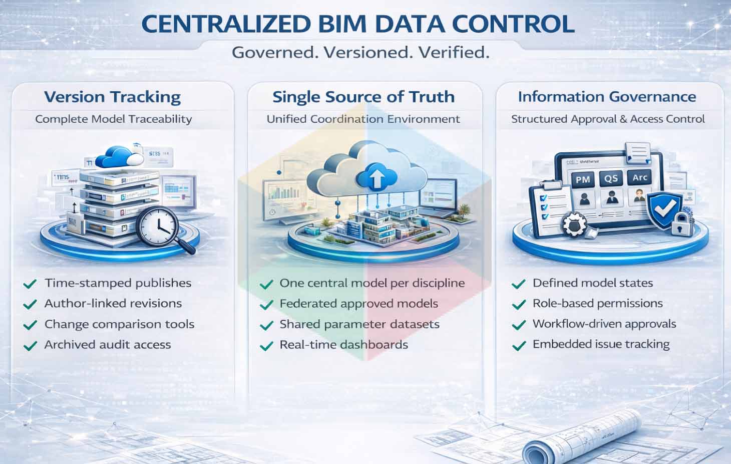
Centralized Data Sharing and Version Control in BIM Projects
Cloud platforms structure building systems coordination around controlled information governance. The CDE manages model versions, publishing status, and approval workflows aligned with project execution plans and BIM standards.
Automated Version History
- Time-stamped publish records for each discipline model
- Author-linked revision metadata
- Model comparison tools highlighting geometric and parameter changes
- Access to archived published versions for audit reference
- Synchronization logs documenting update frequency
Single Source of Truth
- One cloud-hosted central model per discipline
- Federated coordination space referencing approved publish states
- Shared parameter datasets accessible across authorized roles
- Centralized drawing extraction from validated model versions
- Unified dashboards reflecting real time project data
Controlled Information Status
- Defined model states such as Work in Progress, Shared, Published, Approved
- Role-based permissions regulating editing and review access
- Structured approval workflows linked to procurement release stages
- Object-linked issue tracking embedded in the model environment
- Activity logs capturing user interaction with project data
Improving Coordination Between Remote Teams and Stakeholders
Remote teams connect stakeholder designers, consultants, contractors and project managers through a shared model ecosystem hosted in the cloud. The platform structures communication around model objects, system parameters, and updated dashboards. Teams interact with live geometry instead of detached documents, which increases alignment across offices, time zones, and disciplines.
Structured Feedback Loops Through Model-Based Communication
Cloud platforms enable stakeholders to annotate directly within 3D coordination models. Architects, structural engineers, and MEP designers access web based viewers to isolate systems, section congested ceiling zones, and attach comments to specific elements such as ducts, cable trays, valves, or equipment families. The system links each comment to an object ID, location coordinates, and discipline classification. Approval workflows route these annotations to responsible engineers with defined response timelines. This object-linked communication structure organizes feedback around geometry and reduces interpretation gaps during coordination reviews.
Centralized Issue Tracking and Accountability
The cloud environment assigns coordination issues, clashes, and design clarifications to specific users within the project workspace. Each issue includes metadata such as priority level, due date, system type, and spatial zone reference. Engineers resolve geometry conflicts within their authoring tools and synchronize updates back to the cloud.
The platform records status transitions from active to resolved and logs user activity with timestamps. This structured tracking system supports measurable accountability, resolution rate monitoring, and transparent coordination history across remote MEP BIM coordination teams.
Centralized Dashboards for Project Managers
Cloud dashboards present real-time coordination metrics to project managers and BIM leads. These dashboards display clash density trends, model publishing frequency, open versus closed issue ratios, and discipline-specific progress indicators. Managers analyze KPI data to adjust modeling resources, reassign workload in high-density service areas, and sequence coordination reviews based on congestion levels. Live visibility into publishing logs and issue aging reports supports proactive schedule control and risk mitigation strategies grounded in current model data.
Multidisciplinary Model Federation and Alignment
Federated cloud models combine architectural, structural, and MEP systems into a unified coordination environment. All stakeholders reference the same published model set during review sessions. Mechanical routing decisions reflect structural beam depths and architectural ceiling profiles, while electrical containment aligns with coordinated service corridors. This unified model visibility supports accurate service spacing, access clearance validation, and plant room layout optimization.
In complex facilities such as hospital-scale projects targeting LOD 500 deliverables aligned with AIA standards, cloud-hosted coordination integrates onshore and offshore teams under a shared execution framework, producing precise geometry, coordinated service layouts, and validated as-built documentation.
Cross-Platform Accessibility for Field and Office Teams
It provides access through office workstations, digital screens and mobile devices. Site engineers open coordinated 3D views to verify installation sequences, inspect hanger locations and confirm equipment clearances directly from the live model. Field teams compare installed services against coordinated geometry without waiting for revised drawing packages. This cross-platform accessibility supports consistent interpretation of MEP BIM coordination data across design offices and construction sites.
Security, Access Control, and Data Protection in Cloud BIM
| Area | Control | Purpose |
|---|---|---|
| Encryption | Data encrypted at rest and in transit | Protects model data during storage and transfer |
| Authentication | Multi-factor authentication | Secures user login access |
| Access Control | Role-based permissions, Discipline-based access | Controls who can view, edit, or approve models, Limits changes to authorized teams |
| Compliance | ISO 27001 / SOC 2, GDPR alignment | Validates certified security standards, Supports regulated data handling |
| Governance | Activity logs, Version history | Tracks user actions and model changes, Records publish cycles with timestamps |
| Continuity | Offline cache, Backup connectivity | Supports modeling during short network drops, Maintains access stability |
Benefits of Cloud-Based MEP BIM for Contractors and Engineers
Continuous Clash Resolution Before Fabrication
The cloud engine runs clash detection after each published model update. Coordinators define clash sets by element category such as ducts vs beams, cable trays vs sprinklers, or pipes vs ceiling grids. The system groups clash by level, gridline, and service zone. Engineers adjust elevations, offsets, and routing paths before issuing spool drawings. Fabrication teams receive coordinated geometry with verified clearances and support spacing.
Fabrication-Ready Quantity Extraction
Approved model versions generate system-based schedules for duct area, pipe length, fitting counts, tray width, and equipment quantities. Contractors extract hanger coordinates, sleeve positions, and bracket spacing directly from the synchronized model. Fabrication workshops use this geometry for CNC cutting, spool generation, and modular assembly without manual recalculation.
Version-Linked Procurement Control
Each published model carries a version ID and timestamp. Procurement teams reference the approved model version when placing equipment and material orders. Quantity take-offs align with the exact geometry state used for coordination. This link between model version and purchase order improves cost tracking accuracy.
Model-Based Installation Sequencing
Cloud-hosted models connect with project schedules to visualize installation order by zone and level. Contractors review service congestion areas before ceiling closure. Field engineers access coordinated 3D views on tablets to verify pipe gradients, duct elevations, and containment spacing during installation.
Structured Issue Tracking with Accountability
Every clash, comment, and approval action includes user ID and timestamp metadata. Engineers close issues after updating routing or resizing elements in the authoring tool. Project managers monitor resolution duration and clash density trends through dashboards.
Global Production with Controlled Synchronization
Distributed modeling teams publish updates to the same central dataset. The platform logs synchronization frequency and tracks discipline progress. Offshore and onshore engineers work in coordinated cycles without file reconstruction.
Reduced Cost Variability Through Early Validation
Since MEP rework can represent up to 30% of change orders, early coordination lowers material waste and redesign effort. Verified geometry reduces site-level modifications, improves quantity precision, and stabilizes construction budgets.
Future of Remote Construction Collaboration with Cloud BIM
Cloud BIM expands from centralized model access to intelligent, data-driven coordination ecosystems. Advanced technologies integrate directly into MEP workflows, enhancing distributed delivery models such as BIM modeling services USA projects. The focus shifts toward predictive analysis, real-time site connectivity, and performance-based design optimization.
IoT Integration
IoT sensors installed onsite transmit operational data directly into the cloud BIM environment. Engineers associate live data streams with corresponding BIM elements such as chillers, AHUs, pumps, transformers, and distribution boards.
Sensor-driven integration supports:
- Real-time equipment performance monitoring
- Energy consumption tracking by system
- Environmental parameter mapping such as temperature and humidity
- Predictive maintenance alerts linked to digital assets
This data exchange forms the technical base for digital twin environments, where asset metadata continuously updates based on operational performance.
Generative Design in MEP Systems
AI-driven generative design tools evaluate:
- Spatial constraints within service corridors
- Hydraulic and airflow performance criteria
- Equipment clearance regulations
- Maintenance accessibility zones
The system produces multiple routing alternatives with measurable outputs such as material quantity, pressure drop values, and clearance compliance percentages. Engineers compare design options using performance-based metrics before finalizing layouts.
5G and Edge Computing
High-speed 5G connectivity enables low-latency synchronization of large, multi-discipline BIM datasets. Distributed teams access updated models instantly without manual file exchange cycles.
Edge computing enhances performance by:
- Processing heavy model rendering closer to user location
- Accelerating point cloud visualization
- Supporting real-time AR overlays onsite
- Reducing latency during federated model navigation
This infrastructure supports remote inspections and real-time coordination sessions across global teams.
AR and VR-Based Coordination
Augmented Reality projects coordinated MEP layouts onto physical construction zones for installation verification. Field teams validate pipe gradients, duct elevations and equipment clearances against the cloud model before fixation.
Virtual Reality allows coordination workshops where stakeholders review plant room layouts, shaft congestion and maintenance access zones within a simulated environment.
Sustainability and Carbon Tracking
Cloud BIM platforms integrate environmental performance analytics directly into coordinated models. Engineers assign embodied carbon values to materials and evaluate lifecycle performance during design stages.
Integrated sustainability tools provide
- Carbon footprint calculations by system
- Lifecycle cost evaluation linked to material selection
- Energy modeling outputs for HVAC performance
- Environmental impact dashboards aligned with project targets
The future of remote construction collaboration with Cloud BIM integrates AI-driven prediction, sensor-based intelligence, high-speed synchronization, and performance analytics. These advancements expand the technical capability of distributed coordination environments and elevate the execution quality of modern MEP BIM workflows.
Conclusion
Cloud BIM centralizes federated MEP models with version-controlled datasets, clash logs, approval workflows, and quantity-linked metadata inside a single live environment. Every routing update, elevation adjustment, and clearance validation is traceable with time-stamped records. Coordinators analyze clash density trends, issue resolution time, and discipline interaction metrics before fabrication release. Field teams access constructible geometry aligned with approved model versions, reducing change orders and material variance at installation stage.